DutchAudioClassics.nl is your ultimate destination for all information related to vintage digital audio equipment from the renowned brands Philips and Marantz.
Our website provides a wide range of resources including technical specifications, photographs, user reviews, and information about the development and technologys of CD players. Stay up to date with the industry developments of the past, not only about the vintage audio equipment but also about the development of the Compact Disc and its technicalities.
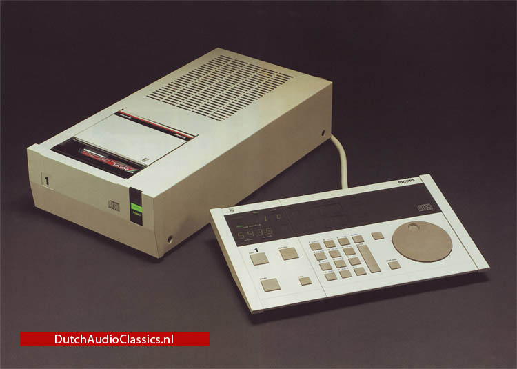


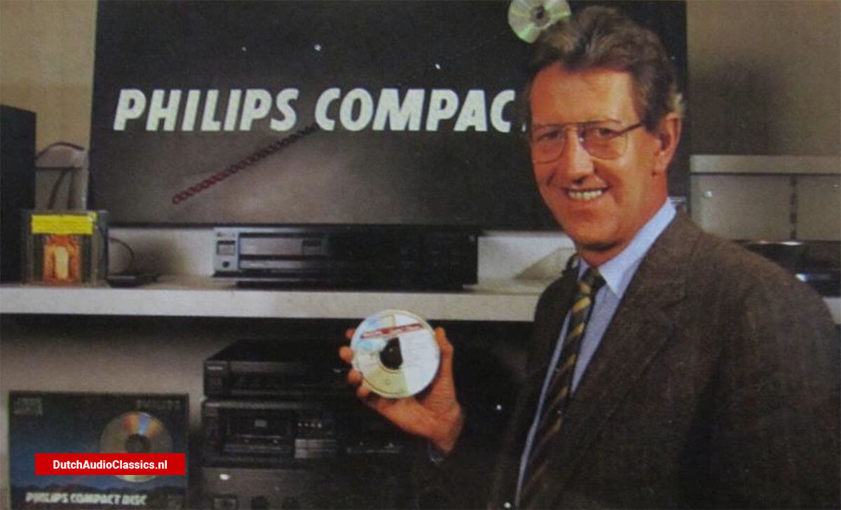
The Dutch inventor of the Compact Disc introduces the Professional LHH2000 Compact Disc player. The professional model for 35,000 Deutsche Mark...


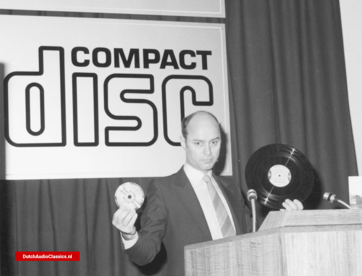
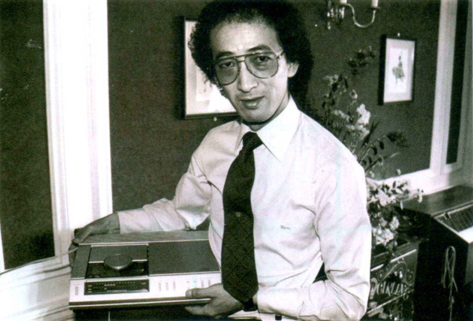
Joop Sinjou started working for Philips in 1952 and throughout his career he worked on the development of audio-video products such as radiogrammofoons, portabels...


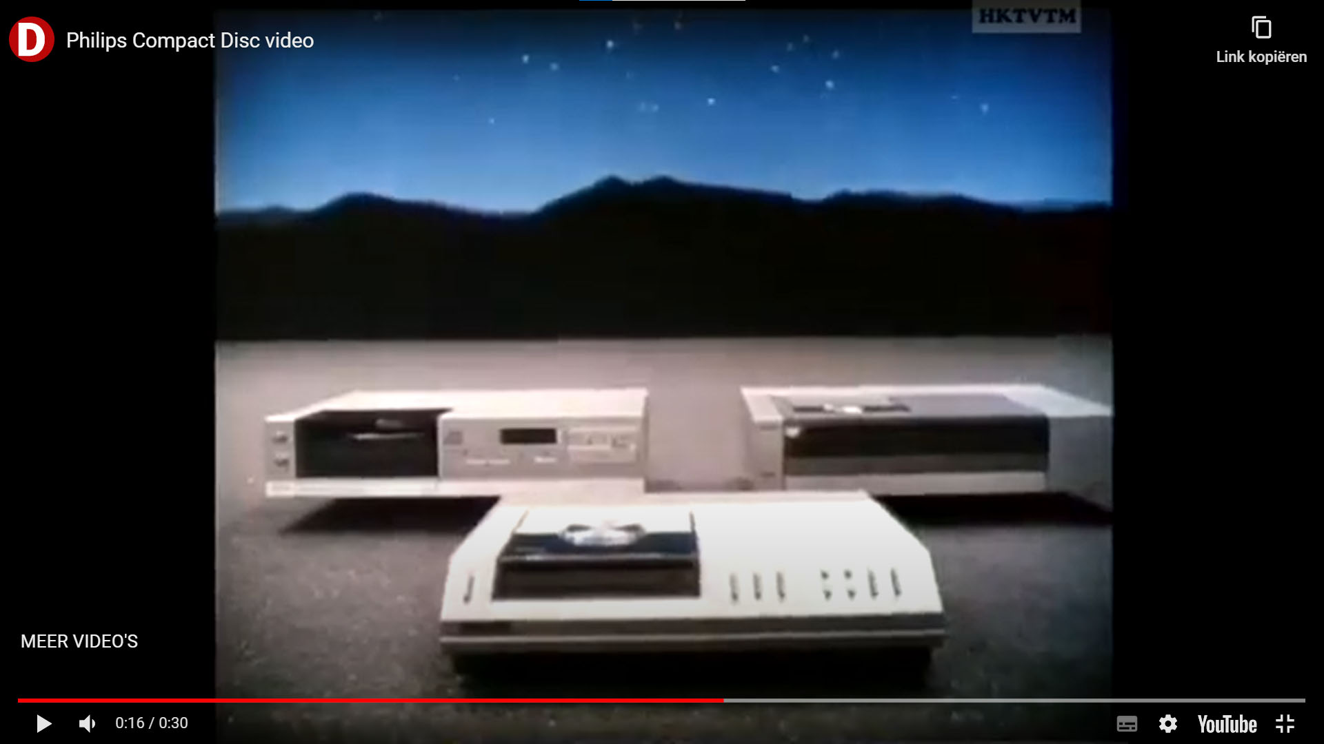
July 1986 - It now seems certain that discs and players for the Philips/Sony Compact Disc digital playback system will be generally available...
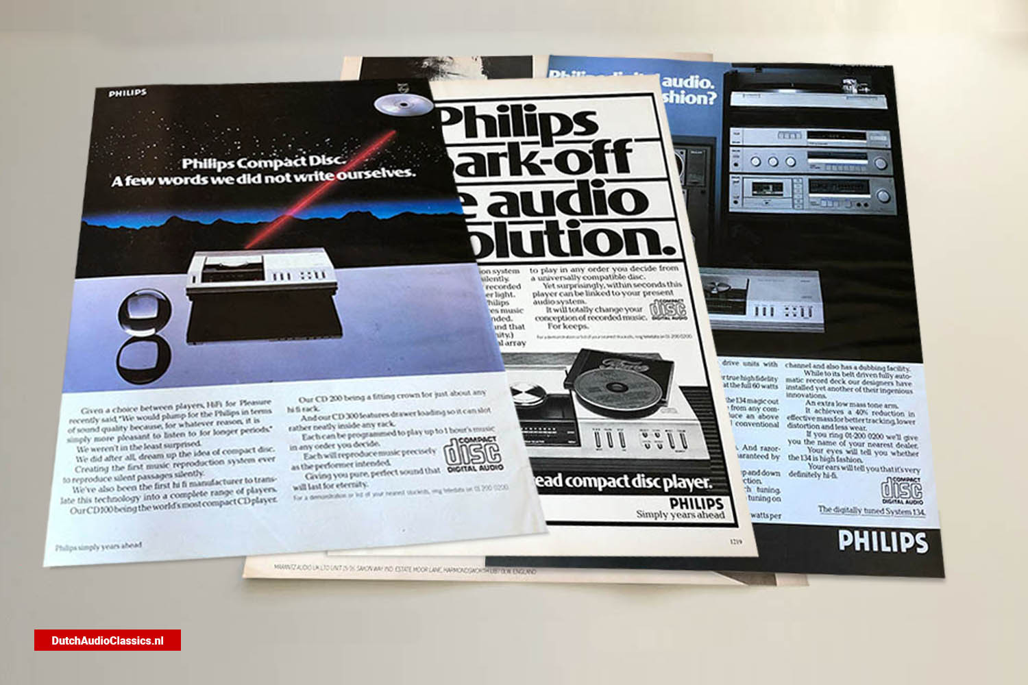
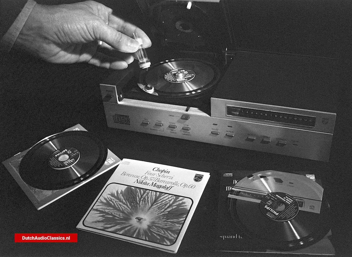
1988 - When the compact disc was introduced at the Dusseldorf Hi-Fi Exhibition in 1982 it came as an revelation. Digital recording on an optical medium was something really new...


The compact disc - the biggest technological breakthrough in home listering since stereo - is launched in Britain this week...

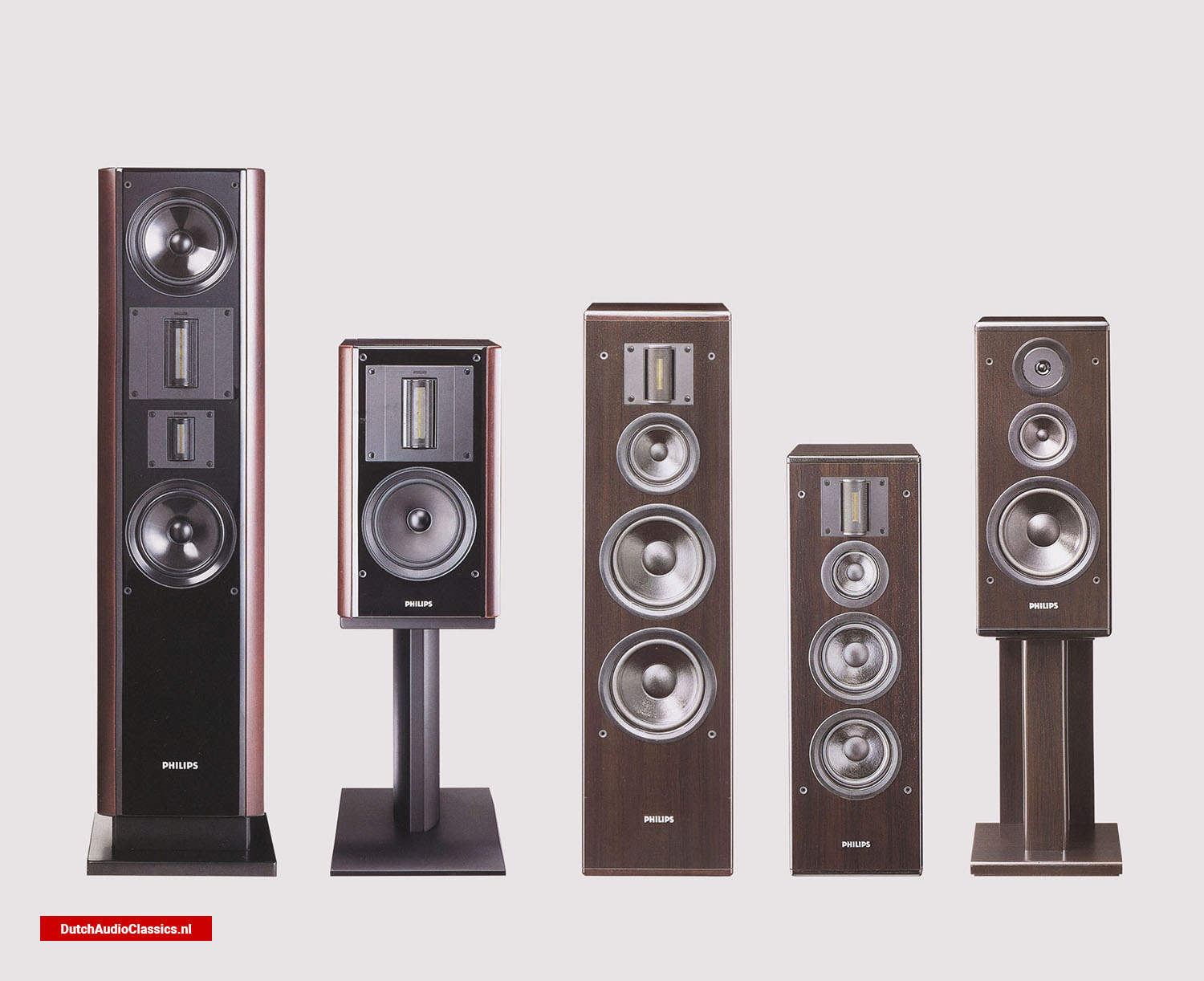
The Philips CD880 cdplayer. Over three-quarters of its parts are made by Philips itself or by its contract suppliers, including the circuit boards...

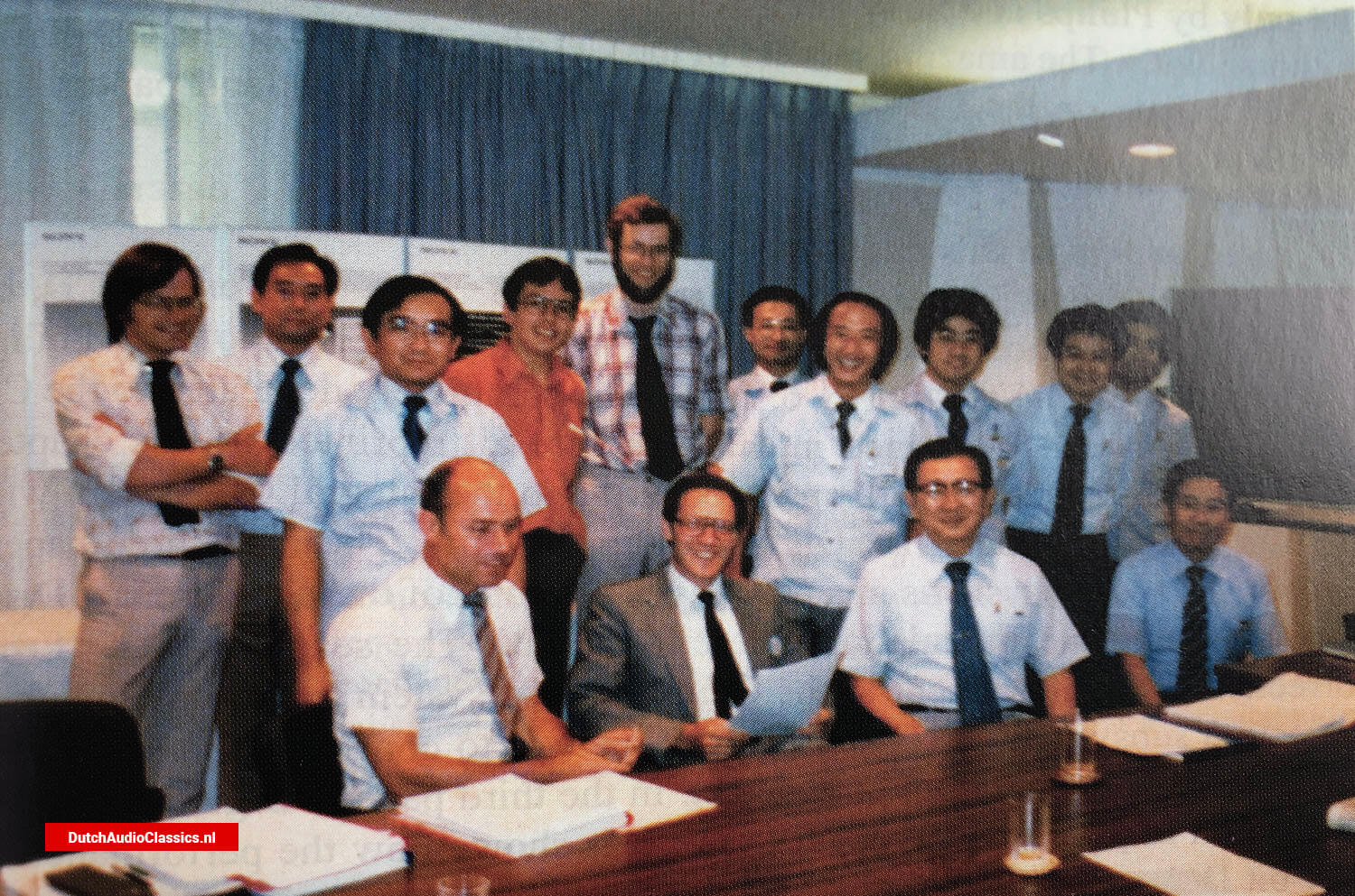
Early this year eleven scientists from the UK, the Netherlands and the USA who have made outstanding contributions...

The Japan Audio Fair in Tokyo and the Audio Engineering Society Convention in New York reliably forecast the Winter CES...
In recent years, most audio components have benefited, at least to some degree, from the use of digital circuitry. No truly digital speaker has yet been created...
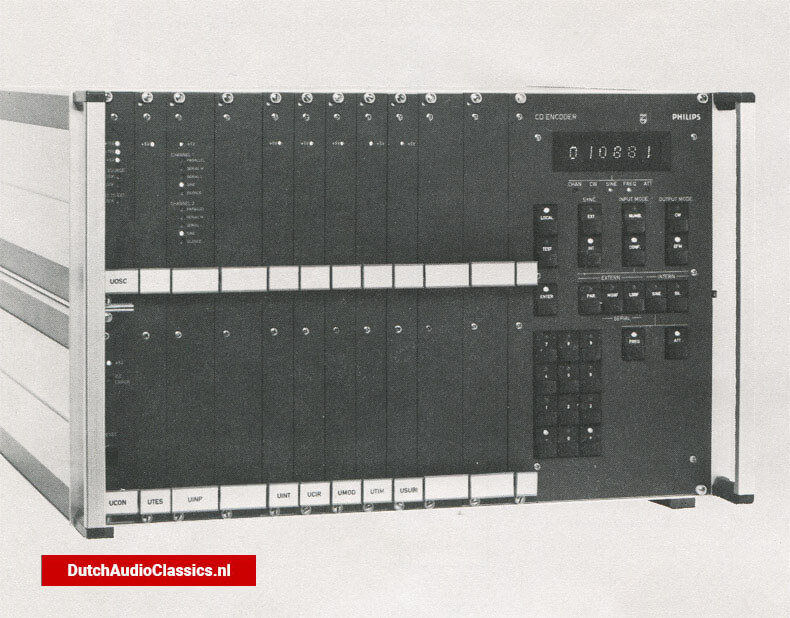
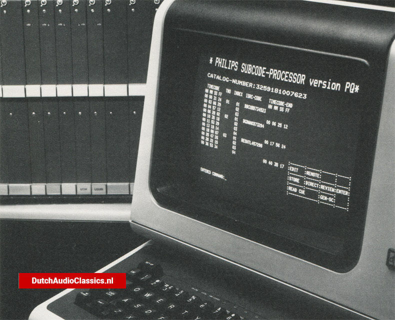
Philips' new CD- Subcode Processor /Editor, the LHH 0425, offers extensive operational facilities for Compact Disc program production houses, and enables significant...

DALLAS April 1986 - Willy Studer A.G. and N.V. Philips Gloeilampenfabrieken announced plans last Monday at the National Assn. of Broadcasters convention...

July 1986 - "Digital" has become the catchword of the decade, with stations clamoring to play the latest CD releases. But promotional benefits aside, are compact discs...

The Marantz DPM7 was build in 1985 as an all-digital amplifier. It was never sold on the market. The DPM7 eventually saw the light of day in 1991 as the AX1000...

April 1984 - The sampling process which converts a digital audio signal from binary numbers back to its original analog form generates spurious frequencies, which must be...


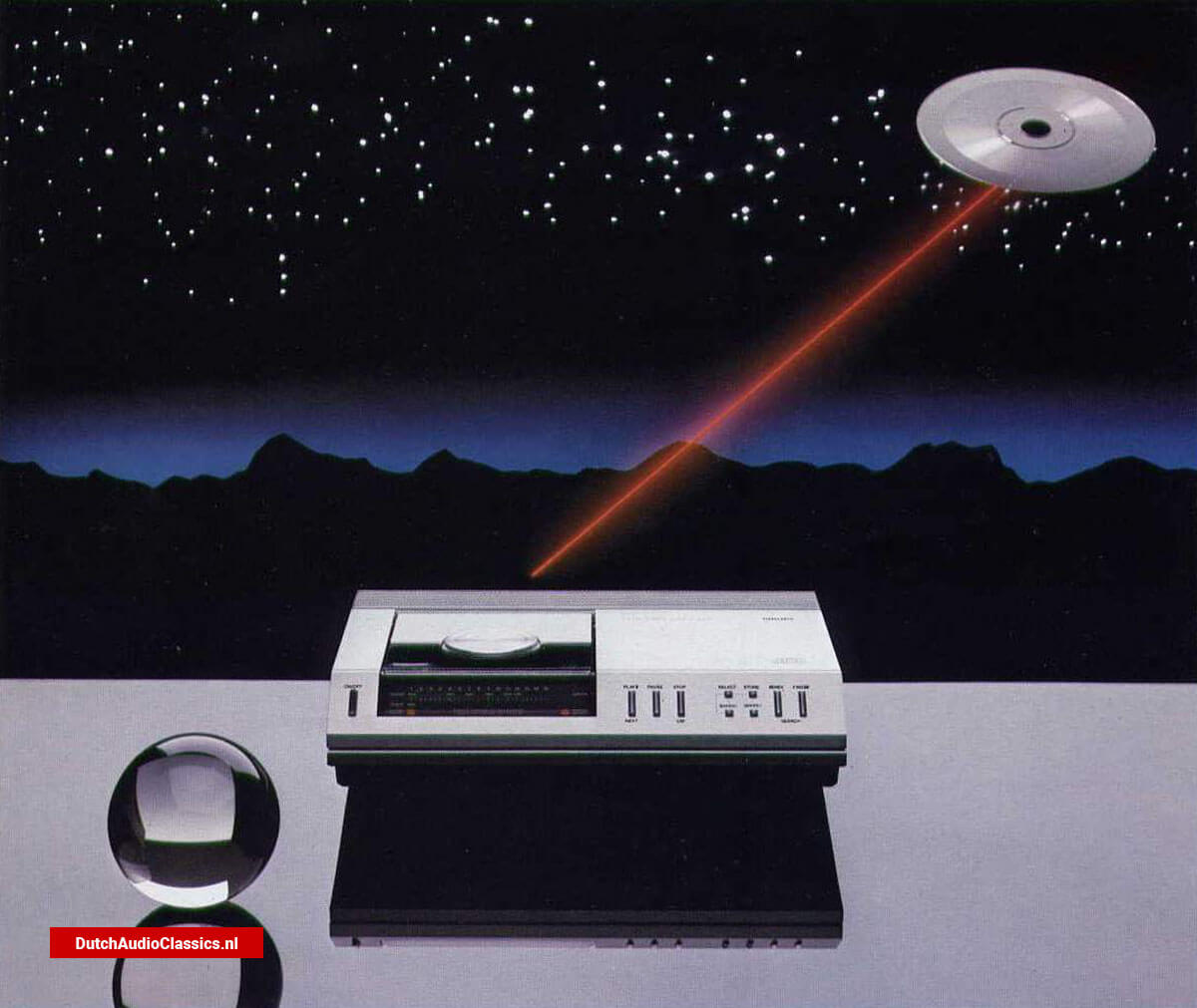
March 1982 - So far, digital -audio recording technology has confined itself to tape. Now, digital discs are about to make Their debut...

November 1972 - Imagine arecord album that will play non -stop for an hour, is small enough to fit in a coat pocket, never wears out or deteriorates with abuse, and, best of all...
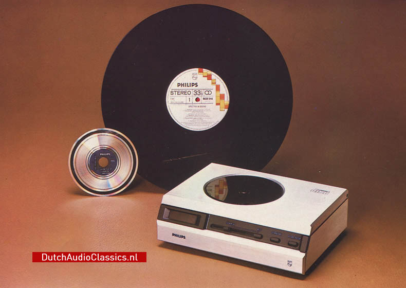
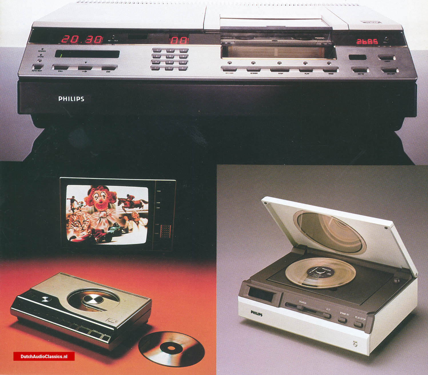
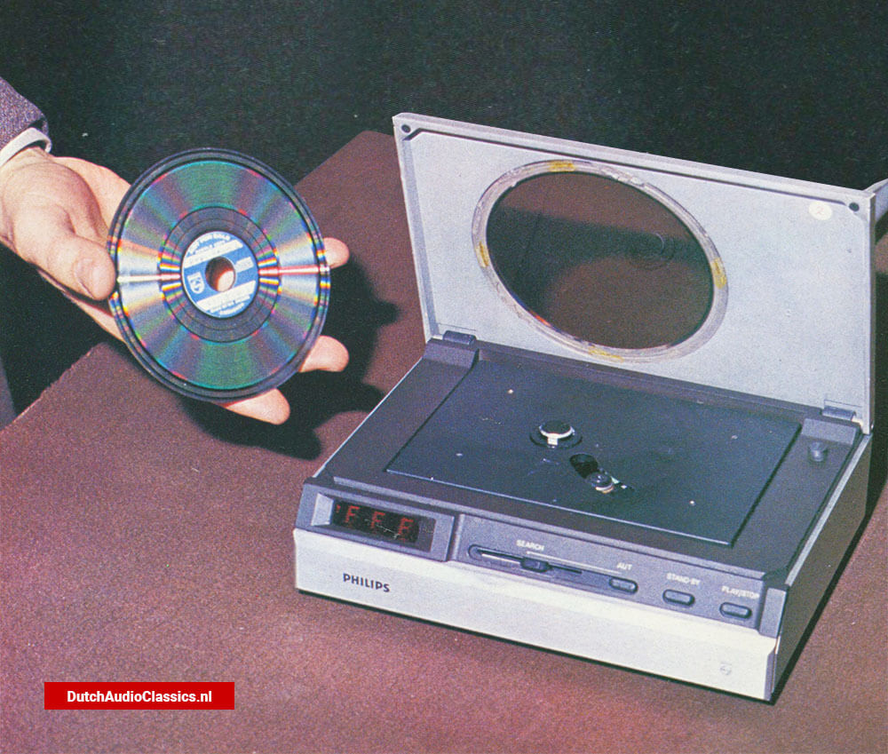
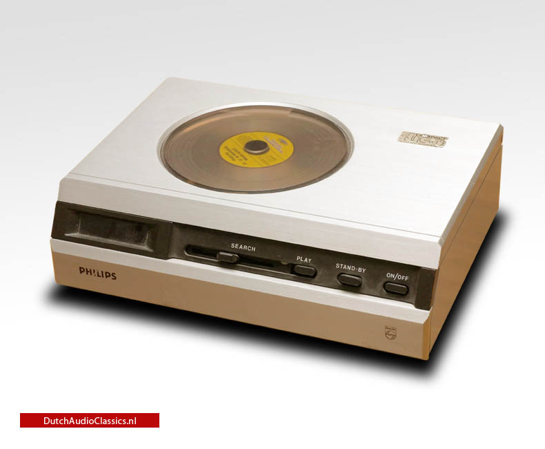
Enjoy new photos of the very first Philips prototype cdplayer, 'Pinkeltje', which Philips showed the world in March 1979

This Marantz CD16 Exclusive is for sale. A true classic. Based on the regular CD16, this Exclusive is developed by Rainer Finck for the German market. The Exclusive version was produced at the end of 1995 in a limited edition of 300.

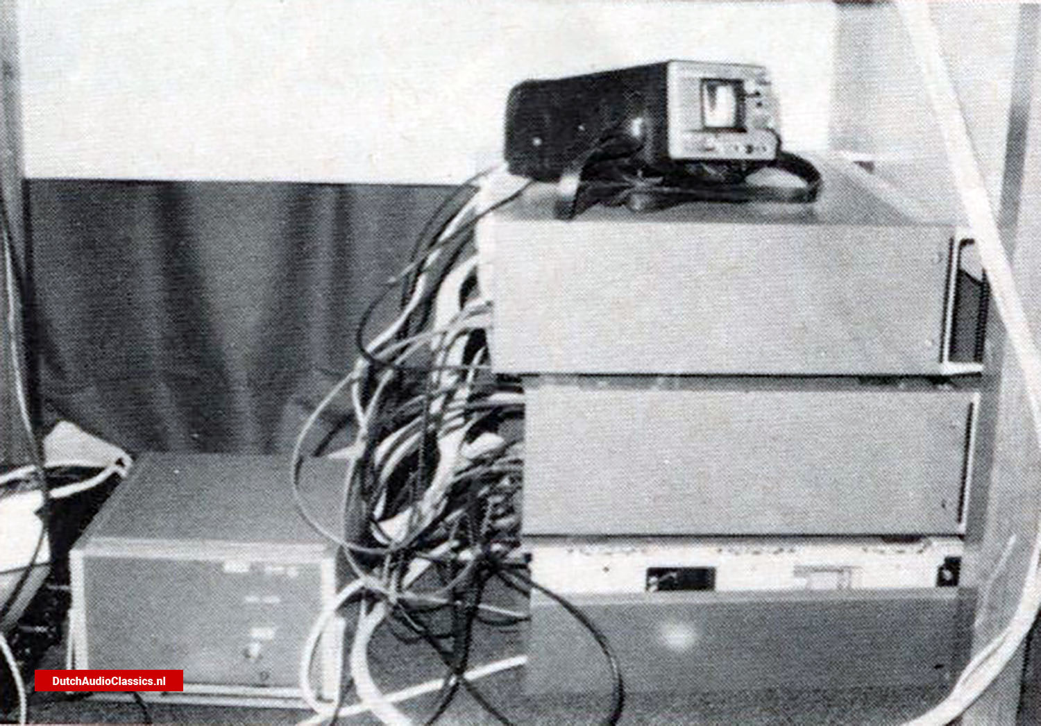
DutchAudioClassics is proud to have obtained photos of a test unit which Philips used to perform tests in order to finalize the Compact Disc format.

Very interesting to see how this prototype was built. If anyone has any information about this prototype, please contact us..

The Philips scd2000 is an handmade multichannel SACD player prototype, build in the year 2000. A stunning looking machine. Only 2 exists. It was used by Philips to demonstrate the new multichannel SACD format..

They both look somewhat the same. A large LCD screen at the left side, and a DCC-cassette-holder with glass/plastic so you are able to see which cassette is inside the portable. The both look very compact...
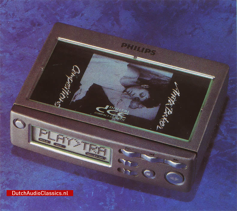
Designed with the aesthetics of the 800 series, the DCC850 Prototype offers a glimpse into an alternate timeline where Digital Compact Cassette (DCC) technology made its debut in the 800 series lineup...

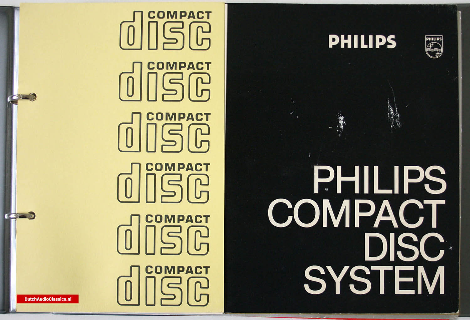
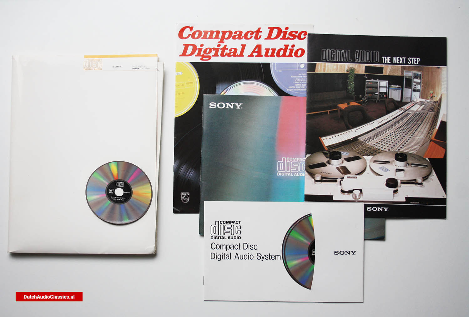
Philips Compact Disc Digital Audio represent an outstanding advance in audio technology. It enables standards of reproduction, previously unattainable through traditional recording, mastering, and replication methods, to become a reality.

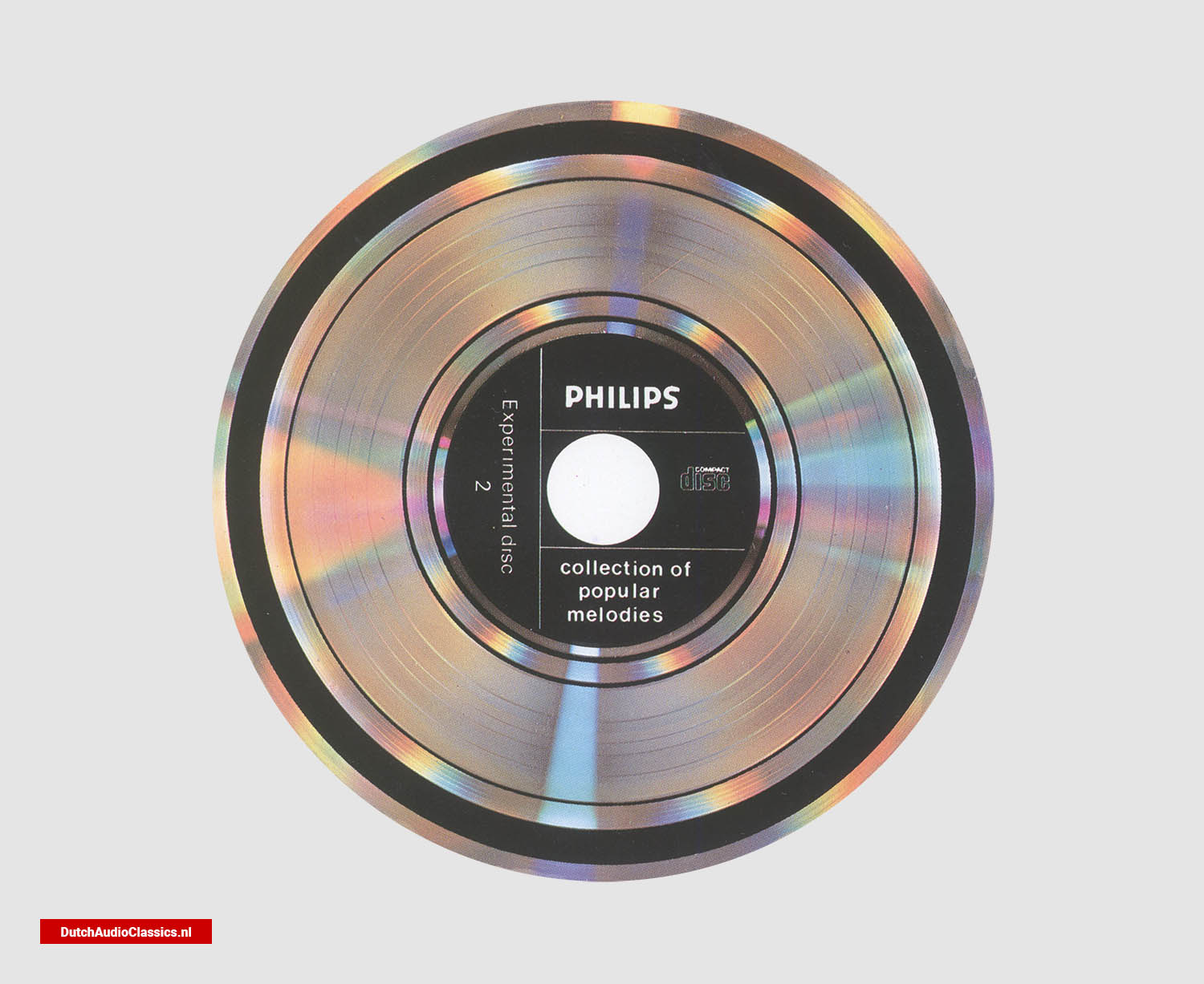
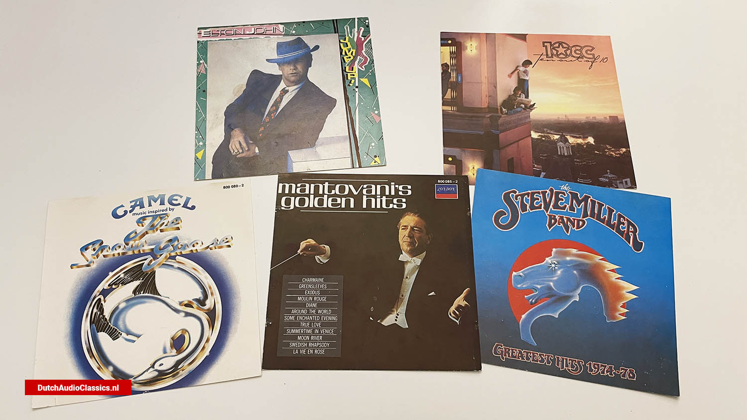
Polygram demonstration compact discs were issued by Philips through its Polygram Records affiliate. These samplers were issued to promote the new Compact Disc format.

The Marantz DPM7 digital amplifier prototype. Build in 1985 as an all-digital amplifier. The DPM7 eventually saw the light of day in 1991 as the AX1000 'audio computer'.

The Marantz CD-16 exclusive is a special edition of the Marantz CD-16 produced specially for the German market developed by Rainer Finck. It was produced at the end of 1995 in a limited edition of 300.

In memoriam Ken Ishiwata (1947 - 2019)
Ken Ishiwata was undoubtedly one of the greatest characters to grace the modern hi-fi world. He was a huge personality, yet emerged from...
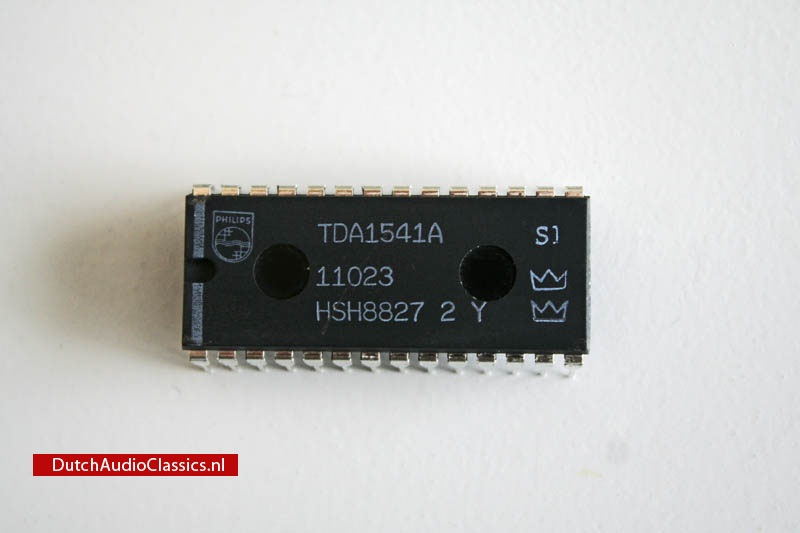
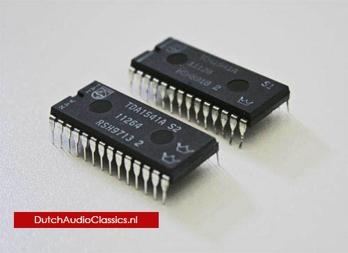
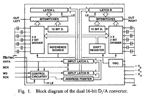
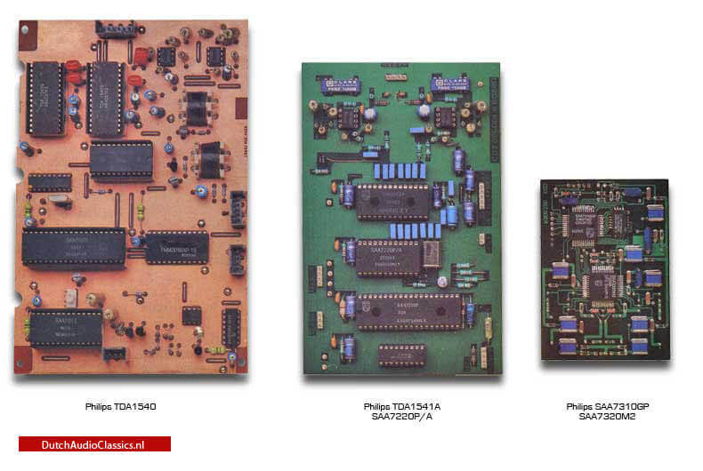
Philips TDA1541A d/a converter
The TDA1541A is a stereo 16-bit digital-to-analog converter (DAC). The ingenious design of the electronic circuit guarantees a high performance...
The Philips TDA1540 is a monolithic integrated 14-bit digital-to-analog converter (DAC). It incorporates a 14-bit input shift register with output...
Watch photos of our large collection Philips and Marantz prototypes.
Compact Disc is the new digital audio medium that uses advanced computer technology to encode up to around 8O minutes of uninterrupted programme material on a disc only 12 cm in diameter...

In digital audio, once sound has been converted by microphones into electrical signals, there is no attempt to replicate the shape of those electrical signals as in conventional LP records...

The original Hyper Dynamic Amplifier Module (HDAM) was first used in the PM-99SE integrated amplifier in 1992. The HDAM is a stamp-sized high-performance...

Ken Ishiwata, a key name behind the Marantz success story in Europe, talks to Ivor Hiunphreys oday's music is very much involved with electronics...

Hi-Fi News’ Editor Steve Fairclough recently visited Marantz’s European HQ in Holland to talk to the company’s famous audio guru Ken Ishiwata. Here is the full interview – only available online...

The Philips DAT880, developed in 1987/1988, is a remarkable piece of audio technology and a testament to the innovation of its time. As one of the first test models of the Digital Audio Tape (DAT) format...

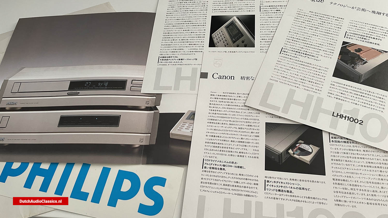
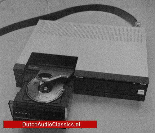
This Top player looks like a medium-sized computer system and has as much together with a conventional player as a Porsche 956 with a Golf GTI. CD innovator Philips has developed and built this perfect CD player...
Philips Compact Disc Digital Audio represent an outstanding advance in audio technology. It enables standards of reproduction, previously unattainable through traditional recording, mastering, and replication methods...

Philips Compact Disc Digital Audio represent an outstanding advance in audio technology. It enables standards of reproduction, previously unattainable through traditional recording, mastering...
The Philips LHH0426 Universal Inspection Players forms the main part of a test system that enables extensive measurements on Compact Disc Masters, Shells, Stampers, and Replicas. Measurements...
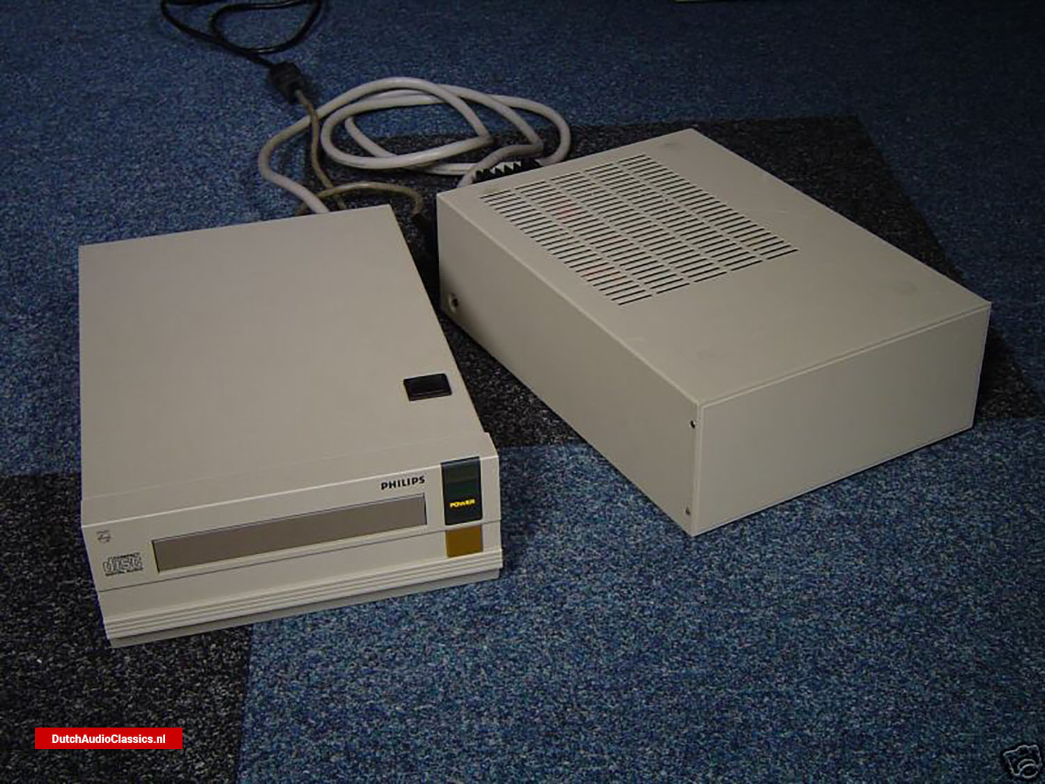
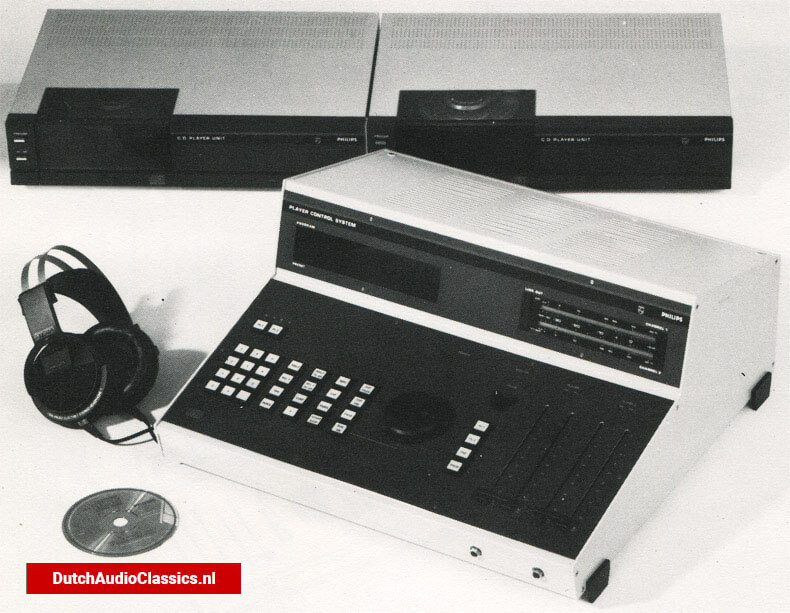
The Philips LHH0501 Professional Compact Disc Player System provides extensive facilities in sound reproduction and editing. It comprises two professional quality compact disc players,...
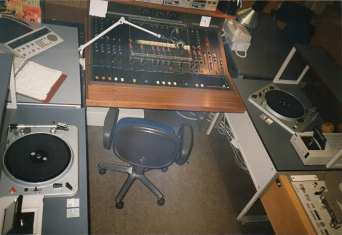
Take a step back in time and relive the golden age of radio broadcasting with our collection of vintage photos featuring the iconic Philips LHH2000 studio CD player....