The TDA1541A is a stereo 16-bit digital-to-analog converter (DAC). The ingenious design of the electronic circuit guarantees a high performance and superior sound quality. The TDA1541A is therefore extremely suitable for use in top-end hi-fi digital audio equipment such as high quality Compact Disc players or digital amplifiers.
Philips TDA1541A d/a converter
All information about the Philips TDA1541A d/a converter

Contents:
- Philips TDA1541
- Philips TDA1541 prototype
- Philips TDA1541 FAQ
- Philips TDA1541 stamp coding
- Philips TDA1541 - A Monolithic Dual 16 Bit D/A Converter
- Grading process of the Philips TDA1541A into standard, R1 and S1 grades
- History of the Philips TDA d/a converter
- The evolution of DAC & the digital filter
- DEM - Dynamic Element Matching for TDA1541 and TDA1541A
- An overview of Philips TDA1541-based cdplayers
- Download PDF: Philips TDA1541 datasheet specifications
Features
- High sound quality
- High performance: low noise and distortion, wide dynamic range
- 4x or 8x oversampling possible
- Selectable two-channel input format
- TTL compatible inputs.
Functional description
The TDA1541A accepts input sample formats in time multiplexed mode or simultaneous mode up to 16-bit word length. The most significant bit (MSB) must always be first. The flexible input data format allows easy interfacing with signal processing chips such as interpolation filters, error correction circuits, pulse code modulation adaptors and audio signal processors (ASP).
The high maximum input bit-rate and fast setting facilitates application in 8 ´ oversampling systems (44.1 kHz to 352.8 kHz or 48 kHz to 384 kHz) with the associated simple analog filtering function (low order, linear phase filter).
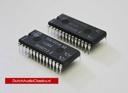
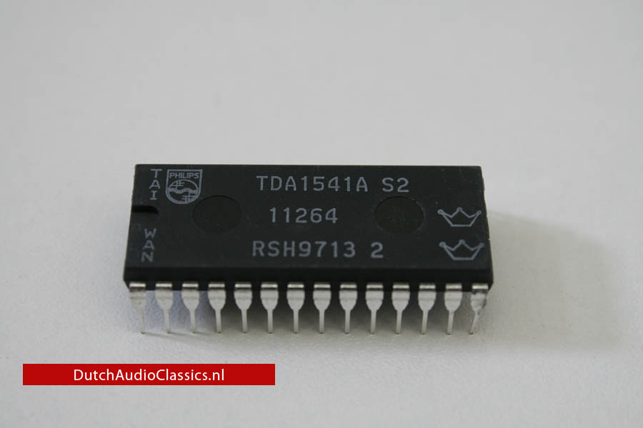 Taiwanese made Philips TDA1541A S2 double crown:
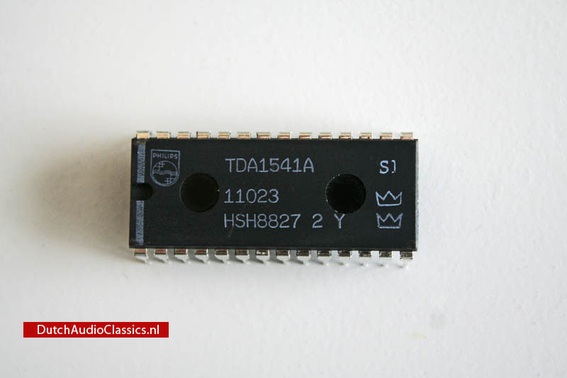 Dutch made Philips TDA1541A S1 double crown:
True 16-bit performance is achieved by each channel using three 2-bit active dividers, operating on the dynamic element matching principle, in combination with a 10-bit passive current divider, based on emitter scaling. All digital inputs are TTL compatible.
| TDA1541A/S2 | TDA1541A/S1 | TDA1541A | TDA1541A/R1 | |
| Typ. THD + N at full-scale at 0 dB | -97 dB | -95 dB | -95 dB | -95 dB |
| Typ. THD + N at 60 dB | -47 dB | -47 dB | -42 dB | -43 dB |
| Channel separation | 98 dB | 98 dB | 98 dB | 98 dB |
| Typ. signal-to-noise ratio | 112 dB | 112 dB | 112 dB | 112 dB |
| Full-scale output current | 4.0 mA | 4.0 mA | 4.0 mA | 4.0 mA |
| Package | DIL28 | DIL28 | DIL28 | DIL28 |
The "select" version TDA1541A S1 progressed to become the TDA1541A S2, with an even stricter selective standard and a so-called double crown mark. In fact, previous "select" product levels were ealisy exceeded through improvements in the manufacturing process and manufacturing precision of the device. The TDA1541A S2 was installed in the Marantz CD-95Ltd together with the SAA7220P/B. Later, Marantz successfully employed the TDA1541A S2 16-bit D/A converter as a finishing touch in the Marantz Project D-1.
Production of the SAA7220P/B digital filter had stopped long before this, so Marantz technicians programmed an 8x over sampling digital filter circuit for use as a high speed DSP.
The legendary 16-bit CD player Marantz CD-7, which is still highly praised, was the last Marantz CD player to feature the TDA1541A S2. Since actual production of the TDA1541A S2 has stopped long before, the number of players that could be produced using this device was limited from the start. Marantz used their precious stock of TDA1541A S2 to design digital filter circuits with high-speed DSPs in the same way as the Marantz Project D-1. The Marantz CD-7 however used 4x over sampling equivalent to the SAA7220P/B and a primary noise shaping circuit modeled on the secondary noise shaping circuitry in the digital filter SAA7030 (used with the first 14-bit DAC TDA1540) but fitted with an on/off function.
Actually, since the phase characteristic could also be calculated, the digital filter was used to calculate the pass-through characteristics of the analog low-pass filter and its phase correction. In other words, the unit was engineered on the premise that the signal output from the CD player would be completely linear and receive no phase correction. In addition, a variety of other technologies have been used during the process of converting the digital signal back to analog. This concludes the history of the Philips multi-bit digital audio DACs.
Philips TDA1541 prototype
This is a Philips TDA1541 prototype chip. It was produced in 1984 at the Philips Anton Niko 3 (A/N3) plant at Nijmegen.

Philips TDA1541 stamp coding
1541 code ABC 1234 (Y):
A: silicon processing facility
B: assembly facility
C: test facility
12: year
34: week
Y: development chip (no standard chip m ask was used)
The names of the facilities are:
A
H: Nijmegen Holland
J: Caen France
R: Hsinchu/TSMC Taiwan
B
H: Nijmegen
S: Kaohsiung Taiwan
B: Hamburg Germany
C
Nijmegen Holland
So a TDA1541A HSH9236 was processed in Nijmegen, assembled in Kaohsiung Taiwan, tested in Nijmegen Holland. It was produced in the year 1992, week 36.
A TDA1541A S2 RSH9713 was processed in Hsinchu/TSMC Taiwan, assembled in Koashiung Taiwan, tested in Nijmegen Holland. It was produced in the year 1997, week 13.
Philips TDA1541 FAQ
- What is a TDA1541 DAC?
-
The TDA1541 series are multi-bit DACs employing a DEM (dynamic ekement matching) circuit.
- What is DEM?
-
To put it simply, DEM (patented by R. van der Plassche) is a superior system developed by Philips technicians that employes 4 to 5 current sources inside the DAC applied in turn to achieve a 1/4 to 1/5 reduction in DAC conversion errors. At first, the TDA1541 was used in combination with the Philips-made SAA7220P/A 4x over sampling digital filter (a noise shaper circuit was not required and was not used).
- When and where was the TDA1541 produced?
-
The TDA1541 (non -A) was launched from 1985 to 1988, and it had no grades. The TDA1541 was specified for exceptional 1/2 LSB linearity. The TDA1541A was produced from 1988 to 1998.
The silicon wafer of the TDA1541 were produced at Philips Nijmegen. Final assembly was at plants in Holland, Taiwan, China or India.
- What grades does the TDA1541A have?
-
The TDA1541A has 4 grades: standard, The R1, the S1 single crown and the S2 double (or gold) crown.
- What does the grades mean?
-
The (standard) TDA1541A is specified at THD+N of 0.8% (-42 dB). The TDA1541A S1 and TDA1541A S2 grades are specified at THD+N of 0.45% (-47 dB) at -60 dBFS. In addition, S2 is specified for THD+N of 0.0014 % (-97 dB) at full level, as opposed to 0.0018% claimed for non S2 grade. The S versions are guaranteed by Philips for this performance, but that does not mean that non S grades can not match the same performance level. Apart from S grades there is also R1 grade. However Philips documentation is a little confusing about it sometimes it is slightly better specified than unmarked TDA1541A, sometimes it is inferior.
There will still be intrinsic errors in DAC linearity due to the tolerance in the alignments of the various masks during the IC production process. As further fine-tuning of the DACs is not possible, Philips has adopted a grading process to pick out those which offer the best performance. When the finished doped and etched silicon wafer emerges from the semi-conductor plant, it carries many dozens of individual DACs. A computer-controlled tester, consisting of 28 needle probes, then connects to the appropiate pads on each raw DAC die, providing power and supplying serial data from a CD player. If a DAC fails to work in this go/no-go test, the result being no analog music output, it is marked with a paint spot. Automatic machinery then slices the wafer into the individual dies and mounts those that passed the initial test in the familiar 28-pin DIL plastic package.
At this stage, the finished TDA1541 ICs are graded by a computer-controlled test station into three classes.
Philips TDA1541 - A Monolithic Dual 16 Bit D/A Converter
IEEE JOURNAL OF SOLID-STATE CIRCUITS, VOL. SC-21, NO. 3, JUNE 1986
HANS J. SCHOUWENAARS, EISE CAREL DIJKMANS, BEN M. J. KUP, AND ED J. M. VAN TUIJL
A monolithic dual high-speed 16-bit D/A converter is described. In the binary weighted current network a dynamic current divider is used to obtain the required high accuracy of the six most significant bits without any adjustment proeedure or trimming techniqne. To construct the ten least significant bits a new approach is used to construct the passive divider stage based on emitter sealing of transistors. As the bk switches are optimized for fast-settling and low-glitch current, both converters can be used without extra sample-and-hold or degtitcher circuitry at sampling frequencies up to 200 kHz. The converter has a differential linearity of 0.5 LSB over a temperature range of 20 to +70ºC. The high linearity of the converter results in a distortion of 0.001 percent over the audio band.
The chip is processed in a standard bipolar process and the die size is 3.8 X 5.5 mm².
I. INTRODUCTION
In high-performance digital audio equipment such as Compact Disc players and digital tape or cassette recorders, the total dynamic behavior of the D/A conversion system plays a very important role. This imposes some strong demands on the D/A converter design such as oversampling capabilities and stereo-signal handling. Oversampling techniques allow digital filtering, which eliminates the need for high-order analog low-pass post-filtering. Phase distortion can affect the stereo information at the high-end of the audio band. Furthermore, oversampling increases the dynamic range of the converter which allows for a digital implementation of tone-control systems. A dualchannel D/A converter approach is used compared to a time-multiplexing system with an extra sample-and-hold function. The extra sample and hold must be applied to avoid phase differences between the two channels at high frequencies. Recently, several techniques were introduced to construct a monolithic high-resolution D/A converter; some of them require high-speed internal digital circuits that interfere with a four-times oversampling capability within an acceptable power dissipation [1]. Another technique uses laser trimming [2], sometimes combined with an increase in process complexity to obtain the required accuracy [3]. However, a low-cost, untrimmed, insensitive to element aging, binary weighted current D/A converter based on dynamic element matching has also been reported [4]. This principle combines passive division with a dynamic system to improve accuracy in a standard process. The principle requires only some noncritical external filter- ing capacitors and is well suited to fit the demands for the D/A converter design. Moreover, the bit current switches can easily be optimized for fast settling with a low-glitch energy in such a way that both converters can be used without external sample-and-hold or deglitcher circuitry. In the new dual 16-bit D/A converter this dynamic element matching principle is used to obtain the required accuracy for the six most significant bits. In order to minimize the number of pins needed for the external capacitors, a rather unusual approach is used to construct the remaining ten binary weighted bit currents. The principle uses emitter scaling of transistors and is based on the basic statistical rule that the relative accuracy improves with the square root of the numbers involved, assuming an uncorrelated distribution between the transistor matching. Another important goal for the dual D/A converter was the design of a flexible serial data input format, which allows an easy interfacing between various digital signal processing devices, operating at different word lengths.
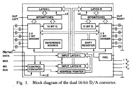 Figure 1
II. GENERAL CONVERTER DIAGRAM
Fig. 1 shows the block diagram with the most important parts of the dual 16-bit D/A converter and shows clearly the dual-channel approach. The reference current source that is common for the two identical converters is fed to three 2-bit dynamic divider stages which perform the required accuracy for the six most significant bits. One output current of the last dynamic divider is fed to the 10-bit passive divider. The 16-bit currents are switched to the output line of the D/A converter by the bit switches which are controlled by the data latches. To minimize timing errors the converter contains on-chip data latches. In order to obtain a low capacitive feedthrough the data input is in a serial mode which requires only four input pins. The digital inputs are TTL compatible and the circuit accepts two different data input formats. An internal emitter-coupled oscillator supplies the dynamic divider stages with the necessary control signals. In the internal digital part a low-voltage swing unsaturated current-mode logic (CML) is used for speed and low-interference noise.
III. THE REFERENCE CURRENT SOURCE
The low-noise reference current source Iref is based on the bandgap of silicon and shows the wellkknown parabolic temperature behavior. With integrated current setting resistors a temperature coefficient of 200 ppm/ºC can beobtained. However, in digital audio applications the dc stability of the reference source is not that important since this temperature depefidence only leads to 0.2-dB gain variation of the output current over a temperature range of 100ºC.
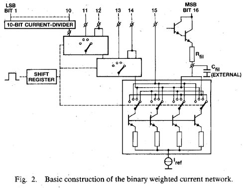 Figure 2
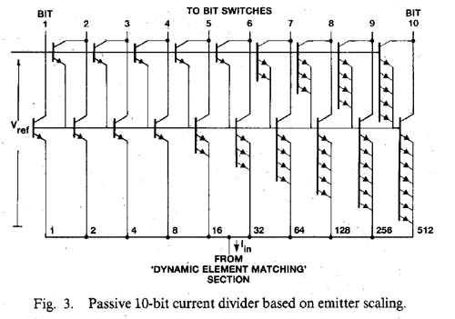 Figure 3
IV. THE BINARY WEIGHTED CURRENT NETWORK
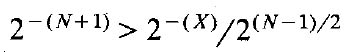
When high sampling rates are required, the binary weighte& currents principle offers the best possibilities to construct a high-performance D/A converter. However, in high-resolution converters this principle sets a high demand on the relative accuracy of the bit currents. To obtain the required accuracy of the six most significant binary weighted bit currents, dynamic element matching is used. Fig. 2 shows the basic construction Of the binary weighted current network of the dual D/A converter. The reference current is divided into four nearly equal parts by means of a passive current divider using resistor matching. The four currents are interchanged during equal time intervals controlled by an internal shift register. The output currents of this dynamic divider stage alll have the same average value with a relative error which ecluals the resistor matching accuracy times the timing accuracy of the interchanging network. The required weighting accuracy between the two MSB currents in a 16-bit D/A converter of 0.5 LSB can easily be obtained. A more complete description of dynamic current division is provided in [4]. Two of these interchanged currents are added to construct the most significant bit current. The third one is fed directly to the bit switches, while the fourth current flows through a second identical dynamic stage. Three of these dynamic divider stages are needed to construct the six MSB currents. The interchanging network consists of Darlington differential pairs which are optimized for base current losses and interchanging frequency. The clock frequency of the interchanging shift register is not related to the sample frequency and is generated by a free-running emitter-ccnpled oscillator which operates at about 250 kHz without affecting the accuracy. A simple low-pass filter is used to remove the ripple of the bit currents due to the interchanging operation to obtain the accuracy and is only drawn here for the MSB. This approach requires seven noncritical external ceramic cttpacitors for each channel. Furthermore, the thermal noise on the bit currents is reduced by the filtering operation down to 120 dB below the maximum output level of the converter. The Darlington stages isolate the filter operation from switching transients of the bit switches. One output current of the last dynaniic divider is fed to the new 10-bit passive divider. Fig. 3 shows the basic concept of the passive current divider based on emitter scaling of transistors. This concept is used for the remaining ten least significant bits. It only consists of 1024 Darlington transistors and does not require any trimming or adjustment procedure and operates over a large temperature range. As all transistors have the same baseemitter voltage, they all have equal collector currents. In this way the input current Iin is divided into 1024 equal currents with a value of one LSB. The output current of the MSB bit of this passive divider is constructed by a combination of 512 collector currents. The required accuracy can only be obtained by carefully randomizing the transistors over the passive current divider surface to eliminate temperature gradients and to minimize mask errors. Assuming a Gaussian distribution between the offset voltages of the transistors, the relative accuracy of the coflector current improves, according to statistics, with the square root of the number of transistor pairs involved. In an N-bit passive current divider the required accuracy is given by
 (1)
(1)
in which
2-(N+l) - the required relative accuracy between two binary weighted output currents ( = 0.5 LSB);
2-(x) - the attainable relative accuracy between two single collector currents; and
2(N-1)/2 - the square root of the number of transistors pairs incorporated in the scaling network.
In a 10-bit binary current network the required accuracy between the two MSB currents has to be < 0.5x 10⁻³. Since the scaling network consists of 512 transistors pairs, the relative error between the collector currents of a single transistor pair has to be <1.1 percent and this implies an offset voltage of 275 µV.
V. THE BIT SWITCHES
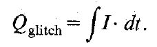
The bit switches are optimized for fast-settling and lowglitch current to avoid the need of extra sample-and-hold or deglitcher circuitry. Due to offset-binary coding, the largest glitch occurs at the zero crossing of the analog output signal. The charge of one glitch is given by the expression
 (2)
(2)
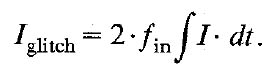
The frequency dependence of the glitch current is now given by
 (3)
(3)
To switch the binary weighted currents to the output line of the D/A converter, three different types of switches are used depending on the value of the bit currents to be switched. To avoid differences in base current losses owing to the different bit currents, the six most significant bits are switched with a fast diode-transistor switch, as is shown in Fig. 4. The diode-transistor switch is controlled by data latches and driven by a differential amplifier.
At the emitter node of the switch a voltage swing of half the collector swing is present. To avoid long settling times due to the parasitic load Zout, a cascode stage is added. To further minimize this parasitic load and to preserve the current generation network from switching transients, an extra cascode stage is added.
The next four bit currents are switched with compensated diode-transistor switches, as shown in Fig. 5. This compensation is added to cancel the voltage swing at the current source connection which causes long settling times as these bit currents are small to discharge the parasitic capacitors. When the bit current is drained to Vref, an extra current Icomp is added to the current source connection and this causes an extra voltage drop over the resistor R, which cancels the voltage swing at the emitter node. Furthermore, a cascode stage is added to minimize the influence of the remaining voltage swing across the parasitic load, which is mainly the collectorsubstrate capacitance of the passive divider.
During switching transients a small amount of compensation current flows into the output line of the converter. An error in the bit current could be introduced depending on the magnitude of the compensation current and the time duration of the current transient. The charge contribution of this current transient can be compared with the charge contribution of one LSB current during one sample period
 (4)
(4)
The compensation current in the bit switch has about the same magnitude as the bit current itself. For bit number N the current Icomp can be written as
 (5)
(5)
Assuming a charge error contribution <0.5 LSB this results in
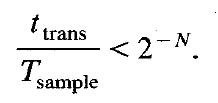 (6)
(6)
For a sampling period of 5 µs and a transient time of 5 ns this compensation method can be used up to the tenth bit. To avoid large glitches in the output current this switching method is not used for the six most significant bits. The six least significant bits are switched to the output line with differential pairs, which are compensated for base current losses. For proper switching of the bit switches it is required to keep the output line of the D/A converter at a well-determined level. Normally an operational amplifier will be applied for this purpose. At the same time this operational amplifier can be used in an active high-order filter network as the output of the D/A converter has to be band-limited to attenuate out-of-band signals dow,l to a sufficiently low level to avoid intermodulati.on distortion in audio amplifiers and recorders.
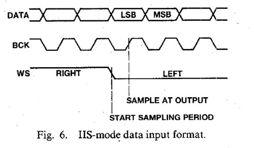
VI. INPUT FORMATS
To allow an easy interfacing between various digital signal processing devices operating at different word lengths, two different data input formats can be used. Fig. 6 shows the first input data format which is based on the Inter IC Signal (IIS) standard, in which the two input channels are time multiplexed. This standard provides an easy interfacing between digital signal processing devices, operating at various word lengths. In this standard three signals are used. The first one is the DATA signal. It consists of a sample of the right channell followed by a sample of the left channel. Any bit length is allowed although the MSB must be the first one. The second one is the BIT CLOCK signal. It is not only used to clock the DATA bits into the input latches, but also to determine exactly the moment at which the sample value appears at the output. The third one is the WORD SELECT signal, which directs the data bits to the left or right channel input latch. A new sampling period starts at the negative slope of the WORD SELECT signal.
 (7)
(7)
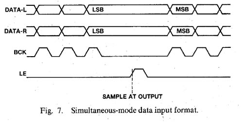
Fig. 7 shows the second possible input data format. In this mode the DATA signals of the left and right channel are applied simultaneously to two different input pins. Only one bit clock signal is used to clock both data signals into the converter. The positive slope of the latch enable signal is used to indicate the end of the data input action and to determine the moment at which the outputs change their sample values. This input format is especially suited for those cases in whi;h the circuits in front of the DAC use a nonstandard serial format.
VII. PRACTICAL D/A CONVERTER CHIP
The circuit is processed in a standard bipolar technology with double-sided isolation and double-layer interconnection. The dual D/A converter needs a chip area of 3.8 X 5.5 mm² and is mounted in a 28-pin dual-in-line plastic package.
 (9)
(9)
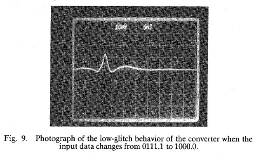
VIII. MEASUREMENTS
Fig. 9 shows a photograph of the most difficult bit transition (from O111.1 to 1000.0) where the largest glitch occurs. The output current of the converter is directly fed into the 50-ohm 1-GHz CRT input. Total glitch charge is within 0.4 pC. The contribution of the glitch current to the output current of the D/A converter is 0.25 ILSB (fin = 19 kHz, ILSB = 62 nA) and thus eliminates the need of extra deglitcher circuitry.
 (10)
(10)
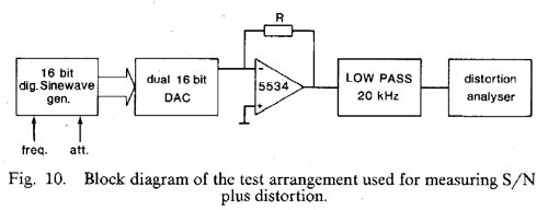
Fig. 10 shows a block diagram of the test arrangement used for measuring signal-to-noise ratio and total harmonic distortion. A true 16-bit digitally generated sine wave is applied to the data input of the dual D/A converter. The feedback resistor of the operational amplifier converts the output current of the converter into a voltage and a low-pass output levels. filter is used to attenuate out-of-band signals. A HP 339A measurement set is used for the measurement of signal-to-noise and total harmonic distortion. The sine-wave generator uses 64K samples of a full-scale sine wave stored in PROMS. An address generator selects the succeeding samples, depending on the desired frequency, in such a way that the quantizing error has no correlation with the sine wave. A 13th-order symmetrical filter with O.1-dB ripple in the 20-kHz passband and 110-dB stopband attenuation above 23 kHz is used for the analog low-pass measuring filter. Furthermore, the filter must have a sufficiently low distortion to avoid that measurement results are being affected.
 (11)
(11)
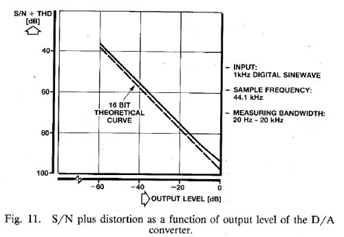
Fig. 11 shows the signal-to-noise ratio plus total harmonic distortion as a function of the signal output level of the D/A converter. The sample frequency is 44.1 kHz and the measuring bandwidth is 20 kHz. At full scale hardly any decrease in signal-to-noise ratio with respect to the 16-bit theoretical curve is found.
Fig. 12 shows the signal-to-noise ratio plus the total harmonic distortion as a function of frequency at different output levels. The converter is used four times oversampled with a sample frequency of 176.4 kHz. Measuring bandwidth is 20 kHz. At full scale a signal-to-noise ratio plus THD of 95 dB over the input frequency range can be obtained. At 20 dB a signal-to-noise ratio of more than 80 dB is measured. This means a dynamic range of over 100 dB.
 (Table I)
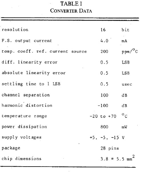
Table I gives some additional data of the dual 16-bit D/A converter.
IX. CONCLUSION
A low-cost untrimmed dual 16-bit D/A converter has been realized in a standard bipolar process using a 6-bit dynamic divider and a 10-bit passive divider to construct the binary weighted current network. The combination of the high linearity and the low distortion with the very flexible input format makes the converter very attractive for application in high-performance digital audio equipment such as compact disc players ancl digital tape or cassette recorders. The very low thermal output noise at 120 dB below rhaximum output level and the fast settling of the bit currents allows the use of oversampling and noise shaping techniques to extend the dynamic range of the converter.
References
[1] - W. D. Mack, M. Horowitz, and R. A. Blauschild, A 14 bit dual-ram DAC for digital-audio systems; IEEE J. Solid-State Circuits, vol SC-17, pp 1118-1126, Dec. 1982.
[2] - J. R. Naylor, A complete high-speed voltage output 16-bit monolithic DAC, IEEE J. Solid-State Circuits, vol. SC-1.8, pp. 729-735, Dec. 1983.
[3] - P. Hollowav. A tnmless 16-bit dieital Dotefitiurneter. in ISSCC Dig. Tech. Papers, Feb. 1984, pp. 66-67.
[4] - R. J. van de Plassche and D. Goedhart, A monolithic 14-bit D/A converter; IEEE J. Solid-State Circuits, vol. SC-14, pp. 552-556, June 1979.
Grading process of the Philips TDA1541A into standard, R1 and S1 grades
 Grading marking stamp
Least Significant Bit (LSB)
The bottom 10 bits control transistor switches on the silicon die, each bit switching twice as many transistors as the one below it. Thus the 16th Least Significant Bit (LSB) switches one transistor, the 15th LSB two transistors, all the way up to the 10th LSB which switches 512 transistors. Provided all the transistors carry the same current when turned on, this arrangement will accurately produce a current output from the DAC proportional to the values of the 10 LSBs in the input word. Matching between the on-chip transistors cannot be maintained to an accuracy better than this, however, so the six Most Significant Bits are handled in a different manner.
 Grading marking stamp
Most Significant Bits (MSB)
Again, they switch transistors controlling currents, but now the sizes of currents are controlled by resistors. Matching is arranged by switching the current-controlling resistors between each transistor switch at a very high frequency. Any errors in the individual currents controlled by each transistor will therefore be averaged out between all the switches by this "Dynamic Element Matching".
Grading process
There will still be intrinsic errors in DAC linearity due to the tolerance in the alignments of the various masks during the IC production process. As further fine-tuning of the DACs is not possible, Philips has adopted a grading process to pick out those which offer the best performance. When the finished doped and etched silicon wafer emerges from the semi-conductor plant, it carries many dozens of individual DACs. A computer-controlled tester, consisting of 28 needle probes, then connects to the appropiate pads on each raw DAC die, providing power and supplying serial data from a CD player. If a DAC fails to work in this go/no-go test, the result being no analog music output, it is marked with a paint spot. Automatic machinery then slices the wafer into the individual dies and mounts those that passed the initial test in the familiar 28-pin DIL plastic package.
At this stage, the finished TDA1541 ICs are graded by a computer-controlled test station into three classes:
TDA1541A - no suffix
The standard grade is guaranteed to have a DLE of less than 1 LSB from bit 1 to 16; this is used in Philips's own reasonably priced players.
TDA1541A - R1
R1 (R for "relaxed) is guaranteed only to have a differential linearity error (DLE) of less than 2 LSBs from bit 1 to bit 16. This grade will be used in inexpensive players and supplied to some third-party manufacturers.
TDA1541A - S1
A small proportion of DACs meet a more stringent performance standard, having a DLE of less than 0.5 LSB for bits 1-7, less than 1 LSB for bits 8-15, and less then 0.75 LSB for bit 16; these are termed the "S" grade and are stamped with a small crown. This top perfoming chip will be used in Philips's best CD players.
History of the Philips TDA d/a converter
"Desperation is the Mother of Invention." Isn't that how the proverb goes? Certainly it applied ten years ago in the case of the Philips engineers working on the development of the Compact Disc system. Given a specification that had included a 14-bit data word length, they had duly developed a 14-bit DAC chip, the TDA1540, only then to be informed that the CD standard decided upon after Sony joined forces with the Dutch company would involve 16-bit data words. (Thank goodness!)
Philips having already committed the 14-bit design to silicon, they would not have a 16-bit DAC ready in time for the medium's launch in the Fall of 1982. They were thus faced with the problem of squeezing four times the resolution from their existing 14-bit DAC. The result was an ingenious digital filter that combined 4x-oversampling and noise-shapingthe latter is effectively a digital feedback loop, the error produced when the filtered digital data are truncated to 14 bits being fed back to the beginningto give a digital system with full 16-bit resolution.
Philips's true 16-bit DAC chip, the TDA1541, followed in 1985, but the seeds of ingenuity had obviously been sown: if the combination of oversampling and noise-shaping can increase the resolution of a DAC using too few bits, then why not go all the way and implement a system that used a simple 1-bit DAC and make up for the shortfall in resolution by taking the oversampling, noise-shaping process to the limit?
The result was a D/A system, internally referred to by Philips as "DAC3" (the two earlier systems were DAC1 and DAC2, of course), which was introduced in the summer of 1989. I discussed the design of the system in detail in June 1989 (Vol.12 No.6, p.57), but briefly, the SAA7321 DAC3 chip massively oversamples the input data at a 256x rate, interpolating the new sample values to produce a 17-bit datastream sampled at 11.02MHz (footnote 1). The data words are then fed to a 1-bit DAC, with the 16-bit error fed back in a noise-shaping loop. Mathematically, this shouldand doesresult in the pulse stream output by the DAC having the full 96dB+ dynamic range of a conventional 16-bit system. But unlike multibit systems, this "Bitstream" DAC is inherently linear and monotonic over its entire rangethe reasons why were given in Peter Mitchell's "Industry Update" in January 1990 (Vol.13 No.1, p.36)requiring no laser-trimming of on-chip resistor values or in-production adjustment of linearity, both of which add to a CD player's manufacturing cost, hence price.
I was told by Philips last year that the Bitstream DAC was therefore intended to be used in low-cost and portable players, the company saying that they would remain with their TD1541-based chip set for high-performance players. Very rapidly, however, once designers had tried the Bitstream approach, it became apparent that, correctly implemented, it could surpass traditional D/A conversion in the preservation of low-level detail. (Even Philips has now introduced a Bitstream player, the LHH500.)
| Type | Description |
Typical THD+N at 0dB (dB) |
Typical THD+N at -60dB (dB) |
Typical SNR (dB) |
Channel Separation |
Max diff. linearity error |
| TDA1541A |
high-performance 16- bit DAC |
-95 | -42 | 112 | 98 | bit 1-16 EdL < 1 LSB |
| TDA1541A / R1 |
high-performance 16- bit DAC |
-95 | -43 | 112 | 98 | bit 1-16 EdL < 2 LSB |
| TDA1541A / S1 |
single crown 16- bit DAC |
-95 | -47 | 112 | 98 |
bit 1-7 EdL < 0.5 LSB bit 8-15 EdL < 1 LSB bit 16 EdL < 0.75 LSB |
| TDA1541A / S2 |
double crown 16- bit DAC |
-97 | -47 | 112 | 98 | N/A |
The evolution of DAC & the digital filter
Multi-bit DACs
Philips TDA1540
The evolution in the use of digital filters and DACs, which greatly influence the sound quality of Super Audio CD/CD players, is also a fascinating topic. In the Red Book, which defines CD standards, the resolution is quoted as being 16 bit.
However, the first DAC used in the first Marantz CD player, the Marantz CD-63, and the Philips LHH-2000, was the 14-bit resolution Philips TDA1540. Since Japanese CD players all employ 16-bit resolution DACs, the Marantz/Philips specification would seem inferior, but according to data taken from actual performance situations and among audiophiles with a good ear for sound quality, the performance of the TDA1540 CD player with its 14-bit DAC is rated outstandingly high.
In actual fact, the secret to the excellent sound produced by the Philips SAA7030 digital filter incorporated into the TDA1540 is not obvious at first. The SAA7030 with a 4x over sampling filter capacity utilizes a top quality noise shaping circuit called a secondary noise shaper. When the Marantz CD-63 went on the market, the effect of noise shaping (imposing frequency characteristics onto distribution of quantized noise in order to shift noise component to an ultra-high ranges that are difficult to hear with the naked ear) was lagerly unknown. The combination of the SAA7030 and TDA1540 used noise shaping to achieve a resolution equivalent to 16-bit.
That's not all. Analog filters built into the analog output circuits after the DACs were set for smooth 3rd order slopes with particular attention given to regularity of the phase characteristics.
At the time, the filter characteristics of Japanese products were set as high as the 9th or 11th order, and the superb sound quality of the Marantz products was overwhelming. The sound quality of the Marantz CD-34 was given high praise as being nearly equal to that of the ultra high-end Philips LHH-2000.
Philips TDA1541
The next DAC developed after the TDA1540 was the 16-bit resolution multi-bit DAC TDA1541, well known among audiophiles. As with the TDA1540, the TDA1541 series are multi-bit DACs employing a DEM (dynamic ekement matching) circuit.
To put it simply, DEM is a superior system developed by Philips technicians that employes 4 to 5 current sources inside the DAC applied in turn to achieve a 1/4 to 1/5 reduction in DAC conversion errors. At first, the TDA1541 was used in combination with the Philips-made SAA7220P/A 4x over sampling digital filter (a noise shaper circuit was not required and was not used).
Philips TDA1541A
The SAA7220P/A digital filters and TDA1541 were slightly improved and re-released as the SAA7220P/B and TDA1541A. These new digital filters conformed to the 28kHz DAT sampling rate, and plans were implemented to improve the precision of DACs. These were incorporated into the Marantz CD-94 after its initial release and also used in the Marantz CD94ltd and Marantz CDA-94.
Philips TDA1541A S1
While the value of Philips multi-bit DACs increased day-by-day, Marantz technicians were trying to achieve an even better sound quality. At about the same time, Philips, who was manufacturing the devices, proposed a special "select" version of the TDA1541A that had a particularly high rate of conversion precision. (Makers often release these kinds of special "select" devices.) Thus, the ultimate 16-bit resolution mutli-bit DAC, the TDA1541A S1, with a carved crown, was born and installed in the Marantz CD-80, Marantz CD-95, Marantz CD-99SE and the Philips LHH-1000. Naturally, the digital filter used in was the SAA7220P/B, which had already gained quite a reputation.
From the audiophile point of view, the TDA1541A S1 was a unique experiment that tested the performance limits of current device technology.
Philips TDA1541A S2
The "select" version TDA1541A S1 progressed to become the TDA1541A S2, with an even stricter selective standard and a so-called double crown mark. In fact, previous "select" product levels were ealisy exceeded through improvements in the manufacturing process and manufacturing precision of the device. The TDA1541A S2 was installed in the Marantz CD-95Ltd together with the SAA7220P/B. Later, Marantz successfully employed the TDA1541A S2 16-bit D/A converter as a finishing touch in the Marantz Project D-1.
Production of the SAA7220P/B digital filter had stopped long before this, so Marantz technicians programmed an 8x over sampling digital filter circuit for use as a high speed DSP.
The legendary 16-bit CD player Marantz CD-7, which is still highly praised, was the last Marantz CD player to feature the TDA1541A S2. Since actual production of the TDA1541A S2 has stopped long before, the number of players that could be produced using this device was limited from the start. Marantz used their precious stock of TDA1541A S2 to design digital filter circuits with high-speed DSPs in the same way as the Marantz Project D-1. The Marantz CD-7 however used 4x over sampling equivalent to the SAA7220P/B and a primary noise shaping circuit modeled on the secondary noise shaping circuitry in the digital filter SAA7030 (used with the first 14-bit DAC TDA1540) but fitted with an on/off function.
Actually, since the phase characteristic could also be calculated, the digital filter was used to calculate the pass-through characteristics of the analog low-pass filter and its phase correction. In other words, the unit was engineered on the premise that the signal output from the CD player would be completely linear and receive no phase correction. In addition, a variety of other technologies have been used during the process of converting the digital signal back to analog. This concludes the history of the Philips multi-bit digital audio DACs.
1-bit DACs
The 1-bit DAC, also referred to as the Bitstream DAC, is based on a completely different concept to that of the multi-bit DACs. Multi-bit DAC rely heavliy on LSI manufacturing precision, Bitstream DACs by and large are not infuenced by such factors, and are characterized by the simplicity of the circuit itsef. Although the linearity of 16-bit DACs is impeccable, production costs are a big drawback. Thus, the current worldwide trend towards cost reduction supports the development of Bitstream DAC.
Philips SAA7320 & Philips SAA7321
Philips developed their first Bitstream DAC, the SAA7320, with a digital filter circuit. This however was not utilized in any Marantz CD players. Their next Bitstream DAC, the SAA7321, featured 4x over sampling and secondary noise shape digital filter circuitry. This was used in the Philips LHH-300 and Philips LHH-500.
Marantz began seriously employing Bitstream DACs from the SAA7350, which incorporated a secondary noise shalping circuit. This DAC was used in conjuction with the newly developed custom made Philips 18-bit output and 8x over sampling digital filter SM5840FP in the Marantz CD-42, Marantz CD-52, Marantz CD-72 and Marantz CD-72a.
Philips DAC7 TDA1547
Advancementin Bitstream DAC technology kept pace with advancements in peripheral devices. The SM5803APT, an 8x over sampling digital filter capable of 20-bit output, and the newly developed "DAC 7" switched capacitor type Bitstream DAC TDA1547, were used in the Marantz CD-15, Marantz C-16, Marantz CD-16SE, Marantz CD-23, Marantz CD-17, Marantz CD-17D and the Philips LHH-700. A secondary noise shaping circuit, the SAA7350, was positioned between the digital filter and the DAC 7. This added the solid feeling of depth found in the multi-bit DACs to the highly praised smoothness and spaciousness of the Bitstream DAC, making it even more desirable.
Philips DF7 TDA1307
The last lot of Marantz Bitstream system CD players used newly developed Philips TDA1307 digital filter that incorporated 8x over sampling and secondary noise shaping circuits (the so-called "DF7") together with the DAC7 (TDA1547), like the Marantz CD-14 and Marantz CD-16D.
Even in the Super Audio CD era, this combination of the TDA1307 and TDA1547 displays real audio quality. This combination was employed in the first Marantz Super Audio CD/CD player, the SA-1. However, the SA-1 uses four TDA1547 circuits per channel, each of which performs a single clock data shift in order to move quantized noised components beyond audible frequencies. In addition, the TDA1307 digital filters are only used for CD playback.
During Super Audio CD playback the 2.8MHz 1-bit delta sigma modulated DSD data is sent directly to the DAC 7.
Cirrus Logic CS4397
Currently, the Cirrus Logic (Crystal Semiconductor) super DAC known as the CS4397 is the main DAC used in new Marantz Super Audio CD/CD players. The CS4397 DAC features a built-in digital filter that enables input of not only Super Audio CD DSD streams but also PCM data up to 192 kHz/24 bits. It also contains a delta sigma modulator and DEM (dynamic element matching) circuitry inherited from the gloriously high fidelity 16-bit DAC TDA1541A S2. A switched capacitor DAC circuit is used in the final stage, and each stage has anti-jitter performance exceeding that of previous 1-bit(Bitstream) DACs. Each CS4397 has a dual channel structure.
Apparently, the same skilled Philips engineers involved in the development of the TDA1541 also participated in the CS4397 DEM circuit. The CS4397 is therefor a super DAC that inherits the tradition of Philips technology.
(source: All about Marantz - stereosound)| Digital filter | fs/noise shaper (n/s) | DAC | Used in model(s) |
| SAA7030 | 4fs.secondary n/s | TDA1540 (14bit) | CD-63 (1982), CD-73 (1983), CD-34 (1985), (LHH2000 (1981) |
| SAA7220 P/A | 4fs (no n/s) | TDA1541 (16bit) | CD-65 (1985), CD-75 (1986), CD-94Ltd, CD-50 (1989) |
| SAA7220 P/B | 4fs (no n/s) | TDA1541A (16bit) | CD-94 (from mid-production), CDA-94Ltd, CD-60 (1989) |
| SAA7220 P/B | 4fs (no n/s) | TDA1541A S1 (16bit) | (LHH1000 <1987>), CD-80 |
| SAA7220 P/B | 4fs (no n/s) | TDA1541A S2 (16bit) | CD-95Ltd |
| DSP | 8fs (no n/s) | TDA1541A S2 (16bit) | (Project D-1 <1998>) |
| DSP | 4fs (on/off selectable, primary n/s) | TDA1541A S2 (16bit) | CD-7 (1998) |
| SM5840FP | 8fs (16bit in 18bit out) | SAA7350 (2nd n/s BS) | CD-42, CD-52, CD-72 (1991) |
| SM5803APT | 8fs (16bit in 20bit out) | SAA7350 + TDA1547 (DAC7) | (LHH-700 <1991>), CD-15, CD-23 (1994), CD-23D |
| TDA1307 (DF7) | 8fs (secondary n/s) | TDA1547 (DAC7) | CD-17Da (1994), CD-16D |
| TDA1307 (DF7) | 8fs (secondary n/s) | TDA1547 (DAC7) | SA-1 (1999) |
| Cirrus Logic CS4397 (Super Audio CD DAC) | SA-14 (2001), SA-12S1 (2001), SA-17S (2002), SA8260(2003) | ||
DEM - Dynamic Element Matching for TDA1541 and TDA1541A
The TDA1541 contains a 10bit passive current divider and a 6 bit dynamic current divider for each channel. The dynamic current divider uses dynamic element matching to reach the required accuracy. The coarse current divider consists of cascaded divide by two cells which are interchanged with a duty cycle which must be exact 50%.
Now the errors of the passive coarse current divider are averaged, which is first-order noise shaping. A full explanation is given in the Philips Semiconductors data book and in Integrated Analog-to-Digital and Digitalto-Analog Converters by Rudy van der Plassch.
The DEM-oscillator.
The oscillator driving the shift register in the active current divider, the DEM circuit, is an emitter coupled multi vibrator. Between the emitters of this multi vibrator is a capacitor. Crosstalk into the DEM-oscillator causes the duty cycle of this oscillator to deviate from the required 50%. Measuring the current through the DEM capacitor with a current probe showed this crosstalk to be data dependent. In the TDA1541 this capacitor was brought internal which reduced cost but not solved this problem. To our benefit, the DEM-capacitor pins are still bonded out and found on pins 16 and 17. These pins are labelled to be n.c in the data sheet but they are connected. This can be checked with an oscilloscope which shows the expected oscillator triangular waveforms.
The DEM-oscillator frequency
The original frequency was chosen to be 100-200kHz. Interference of this frequency, caused by the data, gives idle tones. Making the DEM frequency a multiple of the sampling frequency causes all errors to fold back on DC. This is why DEMclocking improves the sound. The DEM frequency should be made such that within one sampling period all ALL DEM states are used. This brings us to the choice of 4fs or 8fs, dependent on the speed of the circuits. From this it is clear that clocking the DEM circuit is useful for over-sampled as well as non-oversampled circuits. Over-sampled DACs require a higher DEM clocking frequency which is not always possible.
However, DEM clocking always improves the sound.
The circuit
The circuit has to take over the tail currents of the integrated emitter coupled oscillator which are 200uA. The 10k resistors will give 500uA which gives the required drive. An ac-coupling is chosen because the 200uA is process and temperature dependent. The collector supply for the pnps is chosen from the existing -6V in my Philips CD960. In the TDA1541 data sheet -5V is specified. The dc-value of the DEM-pins is about -9Volts resulting in only 4V reverse bias at start-up. The collectors of the switching transistors do not saturate, I used pnp switching transistors but expect that BC558s also can be used. The capacitor at the DEM-pins, if there, is removed. The 200uA of the current sources in the TDA1541(A) cause some sawtooth on the 1200pf caps. The sawtooth may not cross the threshold voltage of the original DEM oscillator, it is not allowed to oscillate.
Testing
Apart from listening to music, the ultimate test, something can be measured. Using a test signal at about -40dB makes use of both the passive and the active current divider. If there is a non-linearity here, we can measure this as crossover distortion if the error has a fixed phase with the test signal. Otherwise is will have the crosstalk modulated difference frequency between DEM and sampling frequency. The pictures at the right are calculated but have been measured with the oscilloscope.
The TDA1541(A) has some temperature effects but after 20 seconds the chip is isothermal and no effect a seen. With synchronous DEM clocking no crossover distortion is seen or measured on all chips I tried.
Measuring the artifacts of a free running DEM oscillator is with a spectrum analyser or a wave analyser is a problem because of the required low resolution bandwidth. The data dependent crosstalk modulates the frequency. This has as result that to less energy is captured in the low bandwidth.
Overview of Philips TDA1541-based cdplayers
Experience the Legacy of Philips TDA1541 CD Players—a Tribute to Audio Excellence. Journey through audio history with these meticulously crafted CD players, each featuring the iconic Philips TDA1541 DAC chip. From the renowned Philips CD880 to the revered Marantz CD-94, immerse yourself in warm, natural sound. Whether you're an audiophile seeking perfection or simply nostalgic for the golden age of CD playback, these players offer an unparalleled listening experience.
| cdplayer | D/A converter | cdmechanism |
|---|---|---|
| ABBINGDON AMR CD-77 | Philips TDA1541A | Sony |
| ACOUSTIC RESEARCH CD-06SE | Philips TDA1541A | Philips CDM-4 |
| ACOUSTIC RESEARCH CD-06SE | Philips TDA1541A | Philips CDM-4 |
| ADCOM GCD-575 | Philips TDA1541 | AKSS-212B |
| ADCOM GCD-600 | Philips TDA1541 | KSS |
| AIWA DX-M45 | Philips TDA1541 | Philips CDM-4/25 |
| ARCAM ALPHA | Philips TDA1541A | Philips CDM-4/19 |
| ARCAM ALPHA 5 | Philips TDA1541A SAA7220P/B | Philips CDM-9/44 |
| ARCAM ALPHA 5 PLUS | Philips TDA1541A | Philips CDM-9 |
| ARCAM ALPHA PLUS | Philips TDA1541A | |
| ARCAM DELTA 70 | Philips TDA1541 SAA7220P/A | Philips CDM-2 |
| ARCAM DELTA 70.2 | Philips TDA1541-S1 (Single Crown) | Philips CDM-4/11 / CDM-4/31 |
| ARCAM DELTA BOX 1 | Philips TDA1541A | D/A converter |
| ARCAM DELTA BOX 2 | Philips TDA1541A | D/A converter |
| ARISTON CD PLAYER | Philips TDA1541A-S1 (Single Crown) | Philips CDM-4/19 |
| Bang & Olufsen Beogram CDX2 | Philips TDA1541A SAA7220 | Philips CDM-2 |
| Bang & Olufsen Beogram CD3300 | Philips TDA1541 | Philips CDM-2/10 |
| Bang & Olufsen CD5500 | Philips TDA1541A | Philips CDM-4/11 |
| BEARD DAP-1 | 3 x Philips TDA1541A YM3623B | D/A converter |
| BLAUPUNKT CP-2850 | Philips TDA1541 SAA7220P/A | Philips CDM-2/10 / CDM-4/11 |
| BRINKMANN ZENITH | Philips TDA1541 CXD1076 | D/A converter |
| California Audio Labs Aria | Philips TDA1541A SAA7220 | Philips CDM-2 / CDM-4/11 |
| California Audio Labs Aria Delta | Philips TDA1541 SAA7220P/A | Philips CDM-2 |
| California Audio Labs Tempest II | Philips TDA1541 SAA7220P/A | Philips CDM-4/11 |
| California Audio Labs Tercet | Philips TDA1541A SAA7220P/B | Philips CDM-2 / CDM-4/11 |
| CAMBRIDGE AUDIO CD1 | 6 x TDA1540 / 3 x Philips TDA1541 | Philips CDM-1 |
| CAMBRIDGE AUDIO CD2 | 4 x TDA1541 SAA7220 | CDM-2/10 |
| Cambridge Audio CD3 | 4 x TDA1541 | Philips CDM1 MKII |
| Cambridge Audio DAC 3 D/A | 4 x Philips TDA1541A-S1 | D/A converter |
| Cary Audio Design CAD-855 | Philips TDA1541A SAA7220P/B | Philips CDM-4/19 |
| CREEK CD60 | Philips TDA1541A-S1 SAA7220P/B | CDM-4/14 |
| DUAL CD 5150 RC | Philips TDA1541A SAA7220P/B | Philips CDM-4/19 |
| DUGOOD GLORY YEAR | Philips TDA1541A SAA7220 | VAM 1201 |
| EMT 981 PROFESSIONAL | Philips TDA1541A-S1 (Single Crown) | Philips CDM-1 Mk II |
| GRUNDIG CD 35 X-Version | 1 x Philips TDA1541 | Philips CDM-2/29 |
| GRUNDIG CD-903 FineArts | Philips TDA1541A SAA7220P/B | Philips CDM-2 / CDM-4 |
| GRUNDIG CD 8100 | Philips TDA1541 | Philips CDM-2/29 / CDM-4/11 |
| GRUNDIG CD 8200 | Philips TDA1541 | Philips CDM-2/10 |
| GRUNDIG CD 8400 | Philips TDA1541 SAA7220P/A | Philips CDM-2/10 |
| GRUNDIG CD 8400 Mk II | Philips TDA1541A SAA7220P/B | Philips CDM-2 / CDM-4 |
| GRUNDIG CD-9000 FineArts | Philips TDA1541A | Philips CDM-2/29 / CDM-4/11 |
| GRUNDIG CD9009 | 2xTDA1541A/S1 | CDM1mkII |
| Kinergetics Research KCD-20 (New) | Philips TDA1541A-R1 | Philips CDM-4/19 |
| Kinergetics Research KCD-30 | Philips TDA1541A | Philips CDM-2/10 / CDM-4 |
| LECTOR CDP 3T | Philips TDA1541A-S1 (Single Crown) | Philips CDM 12 |
| LECTOR DIGICODE | Philips TDA1541A-S1 (Single Crown) | D/A converter |
| LUXMAN D-500Xs II | Philips TDA1541A-S1 (Single Crown) | Philips CDM-3 |
| MAGNAVOX CDB460 | Philips TDA1541 SAA7220P/A | Philips CDM-2/10 |
| MAGNAVOX CDB465 | Philips TDA1541 | Philips CDM-2 |
| MAGNAVOX CDB470 | Philips TDA1541 SAA7220P/A | Philips CDM-2 |
| MAGNAVOX CDB471 | Philips TDA1541 SAA7220P/A | Philips CDM-2 |
| MAGNAVOX CDB472 | Philips TDA1541 SAA7220P/A | Philips CDM-2 |
| MAGNAVOX CDB473 | Philips TDA1541 SAA7220P/A | Philips CDM-4/11 |
| MAGNAVOX CDB560 | Philips TDA1541 SAA7220P/A | Philips CDM-2 |
| MAGNAVOX CDB582 | Philips TDA1541A SAA7220P/B | Philips CDM-4/19 |
| MAGNAVOX CDB630 | Philips TDA1541A SAA7220P/B | Philips CDM-4/19 |
| MAGNAVOX CDB650 | Philips TDA1541 SAA7220P/A | Philips CDM-2 |
| MARANTZ CD-5L | 1 x Philips TDA1541 SAA7220P/A | Philips CDM-2/10 |
| MARANTZ CD-40 | Philips TDA1541A-R1 | Philips CDM-4/19 |
| MARANTZ CD-50 | Philips TDA1541A SAA7220P/B | Philips CDM-4/19 Composite |
| MARANTZ CD-56 | Philips TDA1541 SAA7220P/A | Philips CDM-2/10 / CDM-4/25 |
| MARANTZ CD-60 | Philips TDA1541A SAA7220P/B | Philips CDM-4/19 Composite |
| MARANTZ CD-65 | Philips TDA1541 SAA7220P/A | Philips CDM-2 |
| MARANTZ CD-65DX | Philips TDA1541A SAA7220P/B | Philips CDM-2/10 / CDM-4/11 |
| MARANTZ CD-65 Gold | Philips TDA1541-S1 SAA7220P/A | Philips CDM-2 |
| MARANTZ CD65 Mk II | Philips TDA1541A SAA7220P/B | Philips CDM-4/11 |
| MARANTZ CD-75 | Philips TDA1541 SAA7220 | Philips CDM-2/10 / CDM-4/25 |
| MARANTZ CD-75DX | Philips TDA1541A SAA7220P/B | Philips CDM-2/10 / CDM-4/11 |
| MARANTZ CD75 Mk II | Philips TDA1541A SAA7220P/B | Philips CDM-1 Mk II |
| MARANTZ CD-84 | 2 x TDA1540 SAA7030 | Philips CDM-1 |
| MARANTZ CD-12 | TDA1541A-S1 (single Crown) | Philips CDM-1 |
| MARANTZ CD7 | 2x TDA1541A-S2 (double crown) | CDM 12.3 PRO |
| MARANTZ CD80 | Philips TDA1541A/S1/Q | CDM1mkII |
| MARANTZ CD-85 | Philips TDA1541A-S1 (Single Crown) | CDM-1 Mk II |
| MARANTZ CD880J | Philips TDA1541A-S1 (Single Crown) | CDM-1 Mk II |
| MARANTZ CD94 | Philips TDA1541A | Philips CDM1 |
| MARANTZ CDA 94 | Philips TDA1541A-S1 (Single Crown) | D/A converter |
| MARANTZ CD94mkII | Philips TDA1541A/S1 | Philips CDM1 |
| MARANTZ CD-95 | 2 x Philips TDA1541A-S1 + 2 x SAA7220P/B | Philips CDM-1 |
| MARANTZ CD-99SE | 2 x TDA1541A-S1 (Single Crown) | Philips CDM-1 |
| MARANTZ CD-99SE Limited | 2 x Philips TDA1541A-S1 (Double Crown) | Philips CDM-1 |
| MARANTZ PROJECT D-1 | 2 x TDA1541A-S2 (Double Crown) | D/A converter |
| MARANTZ CD273 | Philips TDA1541 | Philips CDM-2 |
| MARANTZ CD583 | Philips TDA1541A | Philips CDM-4/19 |
| MARANTZ CD650 | Philips TDA1541 SAA7220P/A | Philips CDM-2/10 / CDM-4/25 |
| MARANTZ CD873 | Philips TDA1541 | Philips CDM-2 / CDM-4/11 |
| MARANTZ CD883 | Philips TDA1541A | Philips CDM-4/19 |
| MARANTZ CDV780 | Philips TDA1541A-S1 (Single Crown) | |
| McCORMACK PRISM II | Philips TDA1541A-R1 SAA7220P/B | Philips CDM-4/19 |
| MCINTOSH MCD7005 | Philips TDA1541A | CDM-2/10 |
| MCINTOSH MCD7007 | Philips TDA1541A-S1 (Single Crown) | Philips CDM-1 |
| Meridian 206 mkII | Philips TDA1541 | |
| MERIDIAN 206 | TDA1541 | |
| MERIDIAN 207 (16-bit) | Philips TDA1541A-S1 (Single Crown) | CDM-1 / CDM-4 |
| MICRO CD-M2 | Philips TDA1541 | Philips CDM-1 |
| MICRO CD-M100 | Philips TDA1541A-S1 (Single Crown) | Philips CDM-1 |
| MICRO CD-M2000X | Philips TDA1541A-S1 (Single Crown) | Philips CDM-1 |
| MICROMEGA CD F1 Premium | Philips TDA1541 | Philips CDM-1 Mk II / CDM-4/26 |
| MICROMEGA CD F1 Pro | Philips TDA1541 | Philips CDM-2/29 / CDM-4/25 |
| MISSION PCM II | Philips TDA1541A | Philips CDM-4/11 |
| MISSION PCM4000 | Philips TDA1541-S1 | Philips CDM-2/10 |
| MISSION PCM7000 | Philips TDA1541-S1 | Philips CDM-2/10 |
| MOD SQUAD PRISM | Philips TDA1541 SAA7220 | Philips CDM-2 |
| MOD SQUAD PRISM II | Philips TDA1541A-R1 SAA7220P/B | Philips CDM-4/19 |
| MUSICAL FIDELITY DIGILOG | Philips TDA1541A | D/A converter |
| NAIM AUDIO CD1 | Philips TDA1541 | Philips CDM-2 |
| NAIM AUDIO CD2 | Philips TDA1541A-S1 (Single Crown) | Philips CDM-9 |
| NAIM AUDIO CD3 | Philips TDA1541A-S1 (Single Crown) | Philips CDM-9 |
| NAIM AUDIO CDI | Philips TDA1541A-S1 (Single Crown) | Philips CDM-4/27 / CDM-9 Pro |
| NAIM AUDIO CDS1 | Philips TDA1541-S1 (Single Crown) | CDM-4/25 |
| NAKAMICHI 1000p | 2 x Philips TDA1541A-S1 (Single Crown) | D/A converter |
| NAKAMICHI CDC-3A | Philips TDA1541A CXD1088 | Pioneer PWY1009 / PWY1010 |
| NAKAMICHI CDC-4A | Philips TDA1541A-S1 | Pioneer PWY1009 / PWY1010 |
| NAKAMICHI DA-101p | 2 x Philips TDA1541A-S1 (Single Crown) | D/A converter |
| NAKAMICHI DA-111p | 2 x Philips TDA1541A-S1 (Single Crown) | D/A converter |
| NAKAMICHI DAC-101 Mobile | 2 x Philips TDA1541A-S1 YM3414 PD0037 | D/A converter |
| NAKAMICHI OMS-20 | Philips TDA1541A CXD1088 | KSS-152A |
| NAKAMICHI CDP-2E | Philips TDA1541A CXD1088 | |
| NEC CD-10 | 2 x TDA1541A-S1 (Single Crown) | KSS-150A |
| NEC CD-620 | Philips TDA1541 | KSS-150A |
| NEC CD-720 | Philips TDA1541 | KSS-150A |
| NEC CD-730 | 2 x Philips TDA1541A | KSS-150A |
| NEC CD-816 | 2 x TDA1541A-S1 (Single Crown) | KSS-150A |
| NEC CD-830DS | 2 x TDA1541A-S1 (Single Crown) | |
| ORELLE CD-100 | Philips TDA1541 | Philips CDM-4 |
| ORELLE CD-100e | Philips TDA1541A / TDA1545A | Philips CDM 12.1 / Panasonic |
| ORELLE CD-160 | Philips TDA1541A-S1 (Single Crown) | Philips CDM-4/19 |
| ORELLE CD100SE | Philips TDA1541A-S1 (Single Crown) | Philips CDM-4 |
| PHILCO CD2471 | Philips TDA1541-R1 SAA7220P/A | Philips CDM-2 / CDM-4/11 |
| PHILIPS CD-60 | Philips TDA1541A SAA7220P/B | Philips CDM-4/19 Composite |
| PHILIPS CD-80 | Philips TDA1541A-S1 (Single Crown) | Philips CDM-1 Mk II |
| PHILIPS CD-85 | Philips TDA1541A-S1 (Single Crown) | Philips CDM-1 Mk II |
| PHILIPS CD160 | Philips TDA1541 SAA7220P/A | Philips CDM-2/10 |
| PHILIPS CD207 | Philips TDA1541 SAA7220P/A TDA1542 | Philips CDM-2-P |
| PHILIPS CD304 Mk II | Philips TDA1541 SAA7220P/A SAA7210P | Philips CDM-1 |
| PHILIPS CD360 | Philips TDA1541 SAA7220P/A | Philips CDM-2/10 / CDM-2/29 |
| PHILIPS CD371 | Philips TDA1541 | Philips CDM-2/29 / CDM-4/11 |
| PHILIPS CD372 | Philips TDA1541 | Philips CDM-2 |
| PHILIPS CD373 | Philips TDA1541 | Philips CDM-2 / CDM-4/11 |
| PHILIPS CD380 | TDA1543 SAA7220 | Philips CDM-4/19 |
| PHILIPS CD450 | Philips TDA1541 SAA7220P/A | Philips CDM-2 |
| PHILIPS CD460 | Philips TDA1541 SAA7220P/A | Philips CDM-2/10 / CDM-4/25 |
| PHILIPS CD465 | Philips TDA1541 | |
| PHILIPS CD470 | Philips TDA1541 | Philips CDM-2 / CDM-4/11 |
| PHILIPS CD471 | Philips TDA1541-R1 SAA7220P/A | Philips CDM-2 / CDM-4/11 |
| PHILIPS CD472 | Philips TDA1541 SAA7220P/A | Philips CDM-2 / CDM-4/11 |
| PHILIPS CD473 | Philips TDA1541 | Philips CDM-2 / CDM-4/11 |
| PHILIPS CD480 | Philips TDA1541 / TDA1543 SAA7220 | Philips CDM-4/19 |
| PHILIPS CD560 | Philips TDA1541 SAA7220P/A | Philips CDM-2/10 / CDM-4/25 |
| PHILIPS CD580 | Philips TDA1541 | |
| PHILIPS CD581 | Philips TDA1541 | Philips CDM-4/19 |
| PHILIPS CD582 | Philips TDA1541A SAA7220P/B | Philips CDM-4/19 |
| PHILIPS CD584 | Philips TDA1541A SAA7220P/B | Philips CDM-4/19 |
| PHILIPS CD620 | Philips TDA1541A SAA7220P/B | Philips CDM-4/19 |
| PHILIPS CD630 | Philips TDA1541A SAA7220P/B | Philips CDM-4/19 |
| PHILIPS CD640 | Philips TDA1541 SAA7220P/A | Philips CDM-2 |
| PHILIPS CD650 | Philips TDA1541 SAA7220P/A SAA7210P | Philips CDM-2/10 / CDM-4/25 |
| PHILIPS CD660 | Philips TDA1541 SAA7220P/A | Philips CDM-2 / CDM-4/11 |
| PHILIPS CD670 | Philips TDA1541 SAA7220P/A | Philips CDM-2/10 / CDM-4/11 |
| PHILIPS CD680 | Philips TDA1541A SAA7220P/B | Philips CDM-2/10 / CDM-4/11 |
| PHILIPS CD770 | Philips TDA1541 SAA7220P/A | Philips CDM-2/10 / CDM-4/11 |
| PHILIPS CD771 | Philips TDA1541 SAA7220P/A | Philips CDM-2 / CDM-4/11 |
| PHILIPS CD780 | Philips TDA1541 SAA7220 | Philips CDM-2 / CDM-4 |
| PHILIPS CD820 | Philips TDA1541A SAA7220P/B | Philips CDM-4/19 Composite |
| PHILIPS CD782 | Philips TDA1541 SAA7220P/A | Philips CDM-2 / CDM-4 |
| PHILIPS CD830 | Philips TDA1541A SAA7220P/B | Philips CDM-4/19 Composite |
| PHILIPS CD880 | Philips TDA1541A-S1 (Single Crown) | Philips CDM-1 Mk II |
| PHILIPS CD960 | Philips TDA1541 SAA7220P/A SAA7210P | Philips CDM-1 |
| PHILIPS CDC586 | Philips TDA1541A | Philips CDM-4/20 |
| PHILIPS CDC875 | Philips TDA1541A | Philips CDM-4/19 |
| PHILIPS CDV496 | Philips TDA1541A SAA7220P/B TDA1542 | Philips CDM-10 |
| PHILIPS DAC960 | 1 x Philips TDA1541A | D/A converter |
| PHILIPS LHH1000 | Philips TDA1541A-S1 (Single Crown) | Philips CDM-1 |
| PIONEER PD-8070 | Philips TDA1541 | |
| PROTON AC-300 Mk II | Philips TDA1541 | Philips CDM-2 / CDM-4 |
| PROTON AC-620 | Philips TDA1541A | Philips CDM-4/19 Composite |
| QUAD 66 | Philips TDA1541A-S1 (Single Crown) | Philips CDM-9 |
| RADFORD WS1 | Philips TDA1541A-S1 (Single Crown) | Philips CDM-1 Mk II |
| RADIOLA CD1006 | Philips TDA1541 SAA7220P/A | Philips CDM-2/10 |
| REVOX B 126 | Philips TDA1541A SAA7220P/B | Philips CDM-1 / CDM-4/27 |
| REVOX B 226 | Philips TDA1541 SAA7220P/A | Philips CDM-1 |
| REVOX B 226 Mk II / Signature | Philips TDA1541A SAA7220P/B | Philips CDM-1 |
| REVOX B 226 S / E | Philips TDA1541A-S1 (Single Crown) | Philips CDM-1 Mk II / CDM-4/26 |
| ROTEL RCD-820B | TDA1541 | |
| ROTEL RCD-855 | Philips TDA1541A-S1 | CDM-4/19 |
| ROTEL RCD-955 | Philips TDA1541 | Philips CDM-4 |
| ROTEL RCD-955AX | Philips TDA1541A SAA7220P/B | Philips CDM-4 |
| SAE D103 | Philips TDA1541 | Philips CDM-2 / CDM-4 |
| SANSUI CD-X211E | Philips TDA1541A-R1 SAA7220P/A | Philips CDM-4/19 |
| SCHNEIDER CD4006 | Philips TDA1541 SAA7220P/A | Philips CDM-2/10 |
| SHERWOOD CDP301R | Philips TDA1541 SAA7220P/A | Philips CDM-2 |
| SONY CDP-68 | 1 x Philips TDA1541 CXD1088 | KSS-150A |
| SONY CDP-207ESD | 1 x Philips TDA1541 CXD1088 | KSS-150A |
| SONY CDP-222ESD | 1 x Philips TDA1541 CXD1088 | KSS-151A |
| SONY CDP-227ESD (Old ver.) | 1 x Philips TDA1541 CXD1088 | KSS-151A |
| SONY CDP-227ESD (New ver.) | 2 x Philips TDA1541A-R1 CXD1144 | KSS-151A |
| SONY CDP-301V | Philips TDA1541 CXD1088 | KSS-210A |
| SONY CDP-307ESD | 1 x Philips TDA1541A CXD1088A | KSS-150A |
| SONY CDP-333ESD | 1 x Philips TDA1541 CXD1088 | Sony BU-1E |
| SONY CDP-337ESD | 2 x Philips TDA1541A CXD1144 | KSS-190A |
| SONY CDP-505ESD | 1 x Philips TDA1541 CXD1088 | KSS-151A |
| SONY CDP-507ESD | 2 x Philips TDA1541A-R1 CXD1144 | KSS-151A |
| SONY CDP-555ESD | 1 x Philips TDA1541A CXD1088Q | Sony BU-1E |
| SONY CDP-605ESD | Philips TDA1541 CXD1088 | Sony BU-1E |
| SONY CDP-705ESD | 1 x Philips TDA1541A CXD1088Q | Sony BU-1E |
| SONY CDP-710 | 1 x Philips TDA1541 CXD1088 | KSS-150A / KSS-210A |
| SONY CDP-750 | 1 x Philips TDA1541 CXD1088 | KSS-210A |
| SONY CDP-910 | 1 x Philips TDA1541 CXD1088 | KSS-151A |
| SONY CDP-950 | 1 x Philips TDA1541A CXD1088A | KSS-150A / KSS-210A |
| SONY CDP-C100 | Philips TDA1541A | KSS-210A |
| SONY CDP-M75 | Philips TDA1541 CXD1088 | KSS-150A / KSS-210A |
| SONY CDP-M95 | Philips TDA1541 CXD1088 | KSS-150A / KSS-210A |
| SONY DAS-R1 | 2 x Philips TDA1541A-S1 CXD1144 | D/A converter |
| SONY LDP-550 | Philips TDA1541 | |
| SPECTRAL SDR-1000 | 2 x Philips TDA1541A-S1 (Single Crown) | Philips CDM-1 |
| STUDER A727 | Philips TDA1541A-S1 (Single Crown) | Philips CDM-1 |
| STUDER A730 | TDA154 1A-S1(Double Crown) | Philips CDM-3 |
| SUDGEN CDT-1 | Philips TDA1541AS1 (single crown) | |
| SUGDEN MASTERCLASS | Philips TDA1541A-S-Crown SAA7220 | CDM 12.1 |
| SUGDEN SDA-1 | Philips TDA1541A-S1 (Single Crown) | D/A converter |
| SUGDEN SDT-1 | Philips TDA1541A-S1 (Single Crown) | Philips CDM-9/44 |
| SUGDEN SDT-1SE | Philips TDA1541A-S1 (Single Crown) | Philips CDM-9 Pro |
| SYLVANIA CD1460 | Philips TDA1541 | Philips CDM-2 |
| SYLVANIA CD1470 | Philips TDA1541 | Philips CDM-2 |
| SYLVANIA CD1473 | Philips TDA1541 SAA7220P/A | Philips CDM-2 |
| T+A CD1000 AC | Philips TDA1541 SAA7220P/A | Philips CDM-2/29 |
| TANDBERG TCP 3015A 16 bit | Philips TDA1541 SAA7220 | Philips CDM-2 |
| TEAC CD-Z5000 | 2 x TDA1541A | KSS-210A |
| TEAC CD-Z5000 | 2 x Philips TDA1541A PD0050 | KSS-210A |
| TEAC D-500 | 2 x TDA1541A-S1 SM5813 | D/A converter |
| TESLA MC 902 | Philips TDA1541 SAA7220P/A | Philips CDM-2/29 |
| TESLA MC 911 | Philips TDA1541A SAA7220P/B | Philips CDM-4/25 |
| TOSHIBA XR-9118 | Philips TDA1541A | Philips CDM-4/11 |
| TOSHIBA XR-9128 | Philips TDA1541A-R1 | Philips CDM-4/11 |
| WOODSIDE WS2 | Philips TDA1541A-S1 (Single Crown) | Philips CDM-1 Mk II |
| YAMAHA CDX-630E | Philips TDA1541A CXD1088 | KSS-150A |
| ZANDEN MODEL 5000 | Philips TDA1541A-S2 (Double Crown) | D/A converter |