This page presents an interview with Tetsu Suzuki about the Philips LHH A700, tracing its path from an internal evaluation amplifier to a production model in the Philips LHH era. Set in the early–mid 1990s context of Philips’ high-end digital development, the discussion focuses on design priorities such as speed, time-domain behaviour, limited use of negative feedback, and practical stability.
The interview also documents concrete engineering choices, including bandwidth targets, thermal structure, power supply sizing, and the rationale behind BTL drive with the LHH 800R.
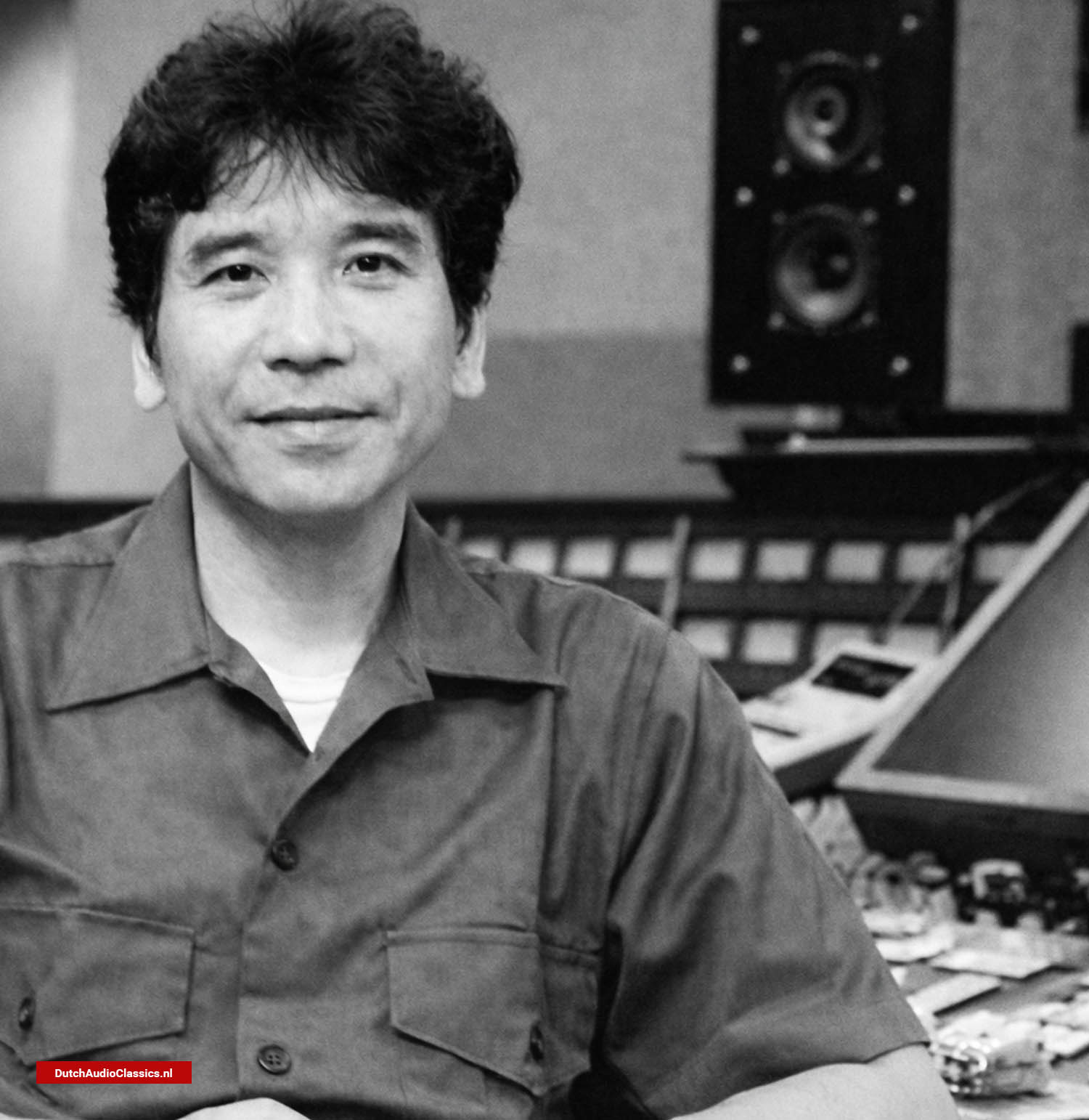
Tetsu Suzuki is a Japanese audio designer whose career spans several of the most respected names in high-end audio. He began his work at NEC, where he was involved in advanced digital audio research and design, including dual D/A converter architectures, the TM3 drive method, and the development of the NEC A-10X amplifier. His approach has always combined technical rigor with careful listening. Beyond engineering, Suzuki is also an active musician, a background that informs his sensitivity to timing, dynamics, and tonal balance. Today, he is best known as the founder and chief designer of SOULNOTE, where he continues to pursue natural, unforced sound through discrete, often non-feedback circuit designs.
Suzuki later joined Marantz and became closely involved in the development of Philips’ LHH series of CD players and related electronics. Within this context, he played a central role in the conception and realization of the Philips LHH A700 power buffer amplifier. The A700 reflects many of his core ideas: minimal use of negative feedback, high-speed operation focused on time-domain accuracy, and a strong emphasis on stability, drive capability, and musical coherence. Together, the LHH series and the A700 illustrate Suzuki’s consistent philosophy across both digital sources and amplification.
The following interview offers a rare look into Suzuki’s thinking during the development of the LHH A700. Rather than presenting a finished product story, it captures his design reasoning, technical priorities, and practical considerations at the moment these ideas were taking shape.
![Tetsu Suzuki LHH Marantz NEX Standard Radio Corporation]() Tetsu Suzuki
Tetsu Suzuki
Could you describe the background and circumstances that led to the development of this amplifier?
Tetsu Suzuki:
It originally began as an internally built amplifier intended for evaluating the sound quality of CD players that were still under development. The previous year, we had commercialized the LHH 500R and 800R CD players, and as we continued evaluating and refining those models, we started to notice the limitations of the amplifiers we were using for listening tests when we pushed for higher sound quality. As the performance of the CD players improved, it became clear that proper evaluation was no longer possible unless the amplifier side could keep up.
That realization is what led us to build a dedicated evaluation amplifier. At that point, however, there was no intention at all to release it as a Philips product.
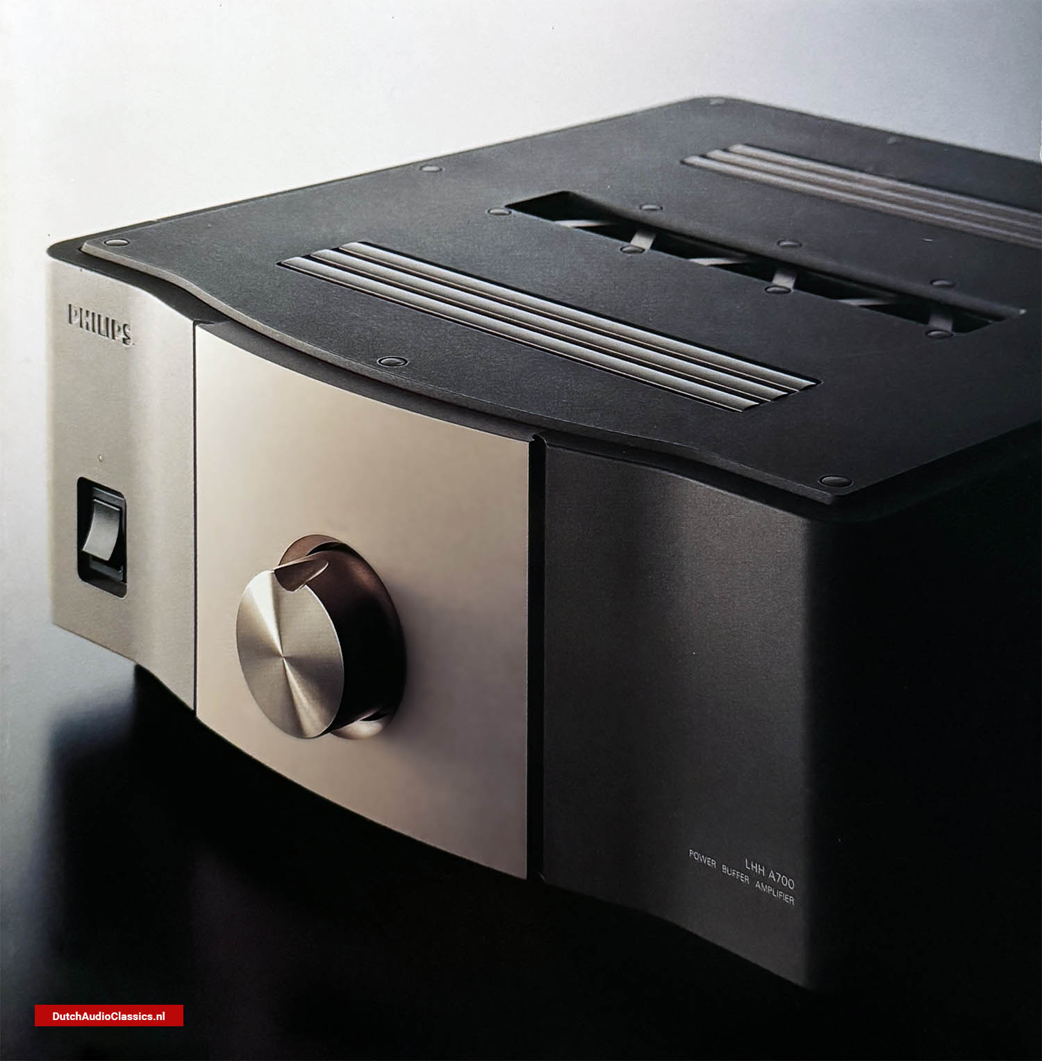
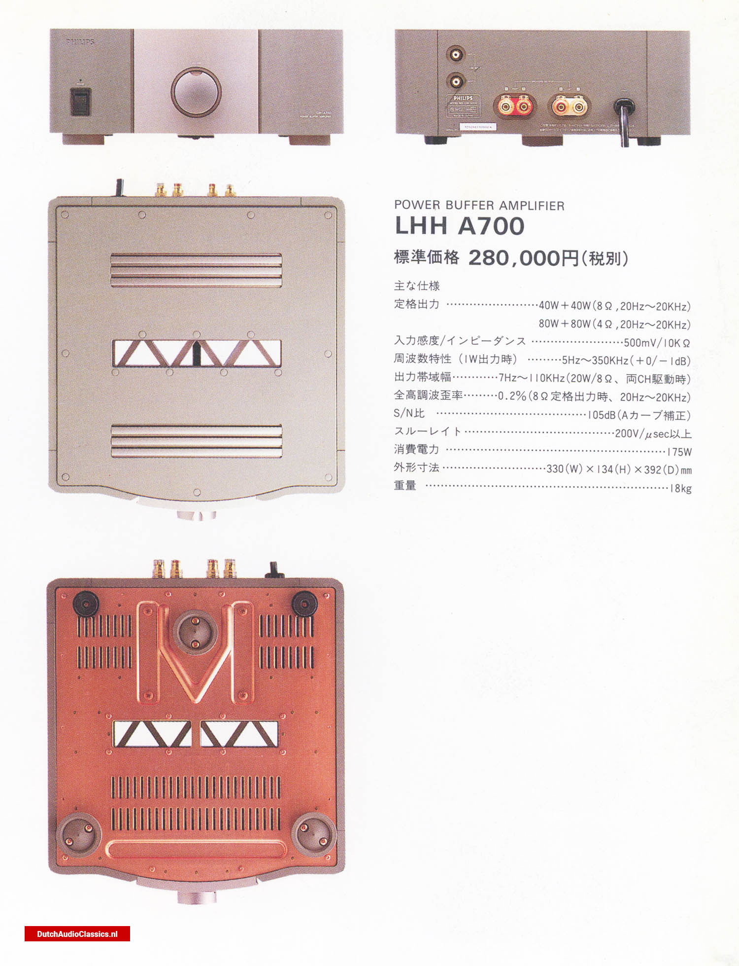
![Tetsu Suzuki Philips LHH A700 Power Buffer Amplifier]() Philips LHH A700 Power Buffer Amplifier
Philips LHH A700 Power Buffer Amplifier
What was the basic concept behind that amplifier, and what kind of performance or characteristics were you aiming for?
Tetsu Suzuki:
The primary focus was on speed, specifically the ability to deliver the required power instantly. In other words, we wanted an amplifier that would be well matched to Philips’ CD players. Those players use a bitstream-type 1-bit DAC, and in order to fully realize the strengths of that approach, the surrounding circuitry needs to be extremely fast. If it is not, various forms of distortion similar to overload effects can begin to appear.
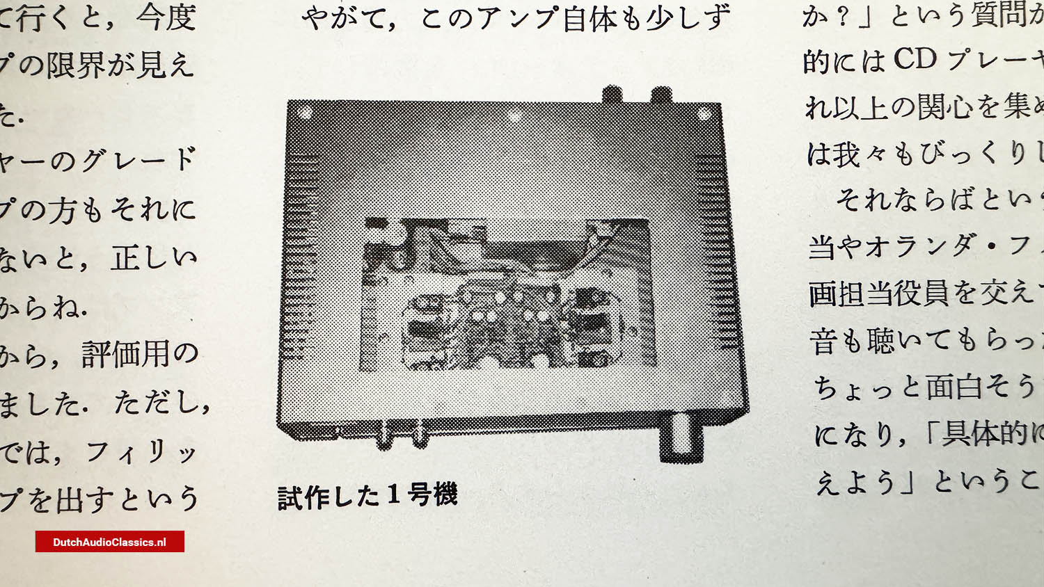
With that in mind, we built a very straightforward, completely handmade power amplifier. The unit shown in the photograph is that amplifier. It was completed in just two days over a single weekend. It was assembled from whatever parts were available at the time and was intended solely for practical use in evaluation. That is also why the input terminals were mounted on the front panel.
![Interview Tetsu Suzuki Philips LHH Marantz Soulnote]() Early prototype of the Philips LHH A700, used as the foundation for the amplifier’s final circuit and mechanical design.
Early prototype of the Philips LHH A700, used as the foundation for the amplifier’s final circuit and mechanical design.
How was this evaluation amplifier received once development progressed?
Tetsu Suzuki:
As the CD players continued to improve, this amplifier began to stand out as well, with reactions along the lines of, “It sounds better than anything we’ve heard so far.” At that stage, we began to sense that there might be room for an amplifier that followed a different direction from previous designs. Even so, there was still absolutely no plan to turn it into a commercial product. We simply continued to refine it gradually, making incremental improvements over time.
Then, at the audio fair held the previous year, when we demonstrated the Philips LHH 800R at the Philips booth, we decided to use this handmade amplifier instead of one from another manufacturer, simply because it was available.
At that stage, was the unit you were using still considered a prototype, or had it already begun to take a more finished form?
Tetsu Suzuki:
Yes, it was still a prototype. After the event, however, visitors began asking us repeatedly, “What is that amplifier you were using?” Even when we explained that it was not a product and had nothing to do with any commercial plans, they continued to ask whether it would eventually be released. These questions kept coming, and as a result, the amplifier ended up drawing almost as much attention as the CD players themselves. That was quite unexpected for us.
In response, we discussed the situation with the sales department and the product planning team at Philips in the Netherlands. After they had a chance to listen to it, their reaction was simply, “This is interesting,” which led us to begin considering concrete steps toward product development.
Through this process, the concrete direction of development gradually came together, and based on the fundamental concept of an audio amplifier, the project moved forward from that point, taking about a year before the unit was completed.
How to read this interview
What design problem does the Philips LHH A700 address?
The LHH A700 was developed to provide an amplifier capable of matching the speed, resolution, and time-domain accuracy of Philips’ high-end digital sources in the LHH series. It originated from the need for an evaluation amplifier that would not limit the assessment of advanced CD player designs, particularly those using bitstream-based D/A conversion.
Which technical principles define the LHH A700’s circuit design?
The amplifier is defined by a minimalist signal path, very wide bandwidth, and a deliberate reduction of negative feedback, especially in the output stage. Design choices emphasize fast transient response, stable square-wave behaviour, low output impedance, and thermal stability, supported by a robust power supply and a mechanically rigid enclosure.
How does the interview place the LHH A700 within a larger system context?
The interview explains how the LHH A700 was intended to operate as part of a broader LHH system, particularly in combination with the LHH 800R. Topics such as BTL operation, grounding, phase accuracy, and system-level stability are discussed as integral aspects of achieving coherent sound reproduction rather than isolated amplifier performance.
Design concept
In the catalogue, this amplifier is described as a “power buffer amplifier.” Could you explain what that term means in this context, and how it reflects the underlying design idea?
Tetsu Suzuki:
Our basic concept was to extract the information contained in the CD, and through that, its quality, as directly as possible. In other words, we wanted a highly transparent amplifier to serve as an interface between the CD player and the speakers. For that reason, we felt the need for a clean, high-quality amplifier. That is why we arrived at the term “power buffer amplifier.”
From an operational standpoint, we initially considered using it only in listening rooms, so we assumed a single input system, and we did not include switching functions or a volume control. That was how we started. However, in various respects, we began to feel that the idea of a single-input main amplifier was actually quite interesting.
Recently, standalone D/A converters have been increasing in number among digital devices. Looking at things that way, the D/A converter, in a sense, has become the digital source selector. Because of that, if there is an amplifier with a single input and a volume control, it becomes possible to build a complete system. In addition, since the source is limited to CD only, if the input is a single system, it becomes easier for customers to use.
For these reasons, with the LHH A700 we adopted a design with a single input and a built-in volume control. However, among users who continue to use conventional analog sources, there are people for whom this approach may not be suitable. With that in mind, we thought it might be a good idea to offer, as a separate item for those users, an externally connected line selector that would be aesthetically matched in design. As a result, we prepared the LHH S700, a passive input selector.
![Interview Tetsu Suzuki Philips LHH Marantz Soulnote]()
![Interview Tetsu Suzuki Philips LHH Marantz Soulnote]()
What was the reasoning behind not including a volume control on the input selector itself?
Tetsu Suzuki:
A volume control inevitably adds output impedance. From experience, when a passive volume control is included, it is difficult to achieve the ideal result. I completely agree with that view. If the signal is transmitted at an extremely high level and only attenuated at the final stage, it is acoustically advantageous. In my case, because my power amplifier does not have a volume control, I connect a 10 dB attenuator at the input terminals and feed the transmission signal at +10 dB. In this way, the signal is kept at a high level right up to the input of the power amplifier, raising the transmission level accordingly, which improves clarity and reduces noise.
I also believe it is best to perform the attenuation at the final stage. Therefore, instead of placing the volume control on the selector side, we positioned it on the power amplifier side.
Is this selector unit offered as a separate component as well?
Tetsu Suzuki:
Yes, it is sold separately. For users who want to connect multiple D/A converters to a single amplifier, or for those who want to use it as a full preamplifier, or who want to use it purely as a power amplifier, or who want to purchase just the amplifier on its own, it can also be used as a standard line selector. If users want to use it as a normal line-only amplifier, they simply need to purchase the selector.
The amplifier itself is very compact. Was this a deliberate part of the design from the outset?
Tetsu Suzuki:
That’s right. It is compact in both size and form, almost the size of an LP jacket. Recently, many amplifiers have become very large and heavy. With this amplifier, one of the challenges was to see how much power could be achieved within a practical size. As a result, the design places emphasis not on outward appearance, but on how much instantaneous power can be delivered, focusing on that point.
Despite its modest size and rated output, it appears to have considerable speaker-driving capability. How do you view this aspect of its performance?
Tetsu Suzuki:
Yes, it belongs to a different category from conventional amplifiers. This is Philips’ first amplifier, and in its appearance, form, concept, and sound, we placed great importance on ensuring it would not resemble products from other companies.
Circuit overview
Could you outline the basic circuit configuration?
Tetsu Suzuki:
The signal path (See Figure 1) has been kept as simple and straightforward as possible. The circuit consists of a voltage amplification stage with approximately 40 dB of gain, followed by a current amplification stage with about 20 dB of gain using voltage-stage-only negative feedback, and finally a MOS-FET output stage with 0 dB gain that operates without feedback.
Because the volume control introduces a loss of about 6 dB, the total voltage gain is roughly 34 dB.
![Interview Tetsu Suzuki Philips LHH A700 Power Buffer Amplifier Signal Path]() Figure 1 - Philips LHH A700 signal path
Figure 1 - Philips LHH A700 signal path
Depending on how one looks at it, this could also be considered a pre-main amplifier combining a flat preamplifier with around 34 dB of gain and a unity-gain power amplifier.
Tetsu Suzuki:
That is a valid way of viewing it.
A shunt-type volume control is used here, is that correct?
Tetsu Suzuki:
Yes. I had previously used this approach in NEC’s A-10X, and because it does not cause the sound to become constrained even when attenuated, it works well even at low listening levels while maintaining clarity.
In this volume control, silver-plated resistors are used, and special attention was paid to reducing residual resistance. A characteristic feature is the use of a 5 kΩ, two-series, T-type attenuator, resulting in approximately 90 dB of attenuation range.
In that case, the configuration involves a 5.11 kΩ series resistor at the input, with shunt attenuation provided by the 5 kΩ volume control.
Tetsu Suzuki:
In that case, the configuration involves a 5.11 kΩ series resistor at the input, with shunt attenuation provided by the 5 kΩ volume control.
That seems to be a compromise.
Tetsu Suzuki:
Yes. The idea was to avoid drawing current as much as possible.
Could you describe the specific circuit configuration of the voltage amplification stage?
Tetsu Suzuki:
The design (See Figure 2) focuses heavily on phase characteristics and the time axis. The open-loop bandwidth has been extended to a region approaching 2 MHz.
As the open-loop bandwidth is expanded and the circuit is made higher in speed, the sound tends to become somewhat unnatural.
![Interview Tetsu Suzuki Philips LHH A700 Power Buffer Amplifier circuit configuration of the voltage amplification stage]() Figure 2 - Philips LHH A700 circuit configuration of the voltage amplification stage
Figure 2 - Philips LHH A700 circuit configuration of the voltage amplification stage
In that case, does each stage in the voltage amplification section apply local feedback at the emitter?
Tetsu Suzuki:
Yes, that is correct. In addition, global negative feedback is applied only to the voltage amplification stage, and even then it is limited to around 20 dB. That makes it almost a no-feedback voltage amplification stage. The current amplification stage operates entirely without feedback.
The first stage is a differential balanced circuit, is that correct?
Tetsu Suzuki:
Yes. The input stage is a differential balanced configuration. For both the first and second stages, we use bipolar transistors rather than FETs.
In that case, an input coupling capacitor would be required on the input side.
Tetsu Suzuki:
Even when using a coupling capacitor, bipolar devices are superior in terms of practical operation. From the standpoint of sound quality, they are also better.
Measurement results and technical considerations
In the emitter-coupled differential circuit of the second stage, LEDs are used on the collector side. Are these LEDs the transparent, chip-type LEDs?
Tetsu Suzuki:
Yes, they are used as constant-voltage elements. Two chips are mounted inside a transparent molded case. Each one functions as a constant-voltage element at approximately 3.58 V.
So by placing two chips in the case, you can obtain twice the brightness at the same operating current.
Tetsu Suzuki:
We are not using two chips for brightness. We use a high-luminance type to ensure stable operation. In this circuit, the LED functions as a 3.58 V constant-voltage element.
Is this used for biasing the current amplification stage?
Tetsu Suzuki:
Yes, that’s correct. The output of the current amplification stage is voltage-clamped. For reasons related to sound quality, we do not stabilize the voltage regulator itself, instead using a transistor ripple filter. In this way, voltage fluctuations in the power supply are suppressed before reaching the circuit.
Because the entire circuit is fully symmetrical, the influence of power supply voltage variations is less likely to appear at the output. However, in the second stage, the load seen by the negative feedback network is 27.4 kΩ.
The output of the push-pull stage is voltage-clamped and then received as a low-impedance load. As a result, this contributes to wider bandwidth. For this reason, careful attention was also paid to the wiring patterns of the negative feedback paths, shortening them to around 3 cm. Practical design measures to maintain wide bandwidth are incorporated throughout.
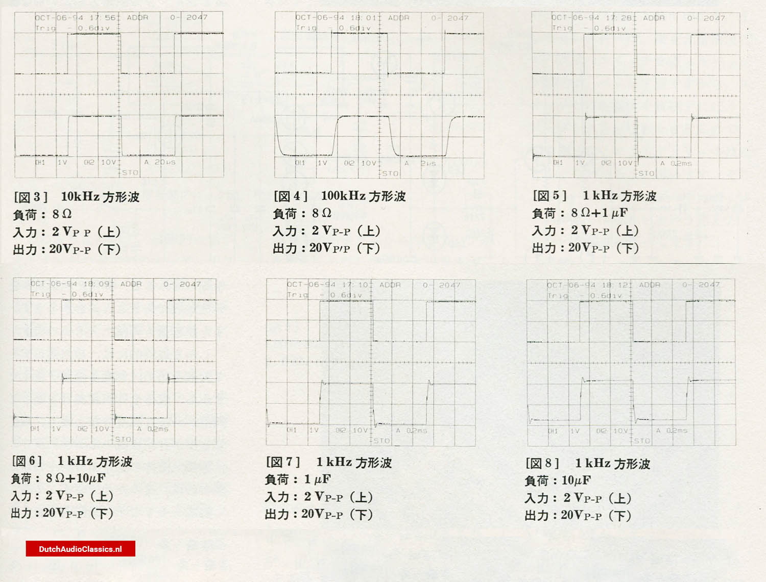
As a result, the square-wave response shown in Figures 3 and 4 is excellent.
In addition, the main power supply requires 80 V or 100 V, and high-voltage components are used for this. This, too, is part of the effort to achieve wide bandwidth. Higher voltage components have lower impedance at high frequencies.
The current amplification stage uses a two-stage Darlington configuration with MOS-FETs, correct?
Tetsu Suzuki:
Yes. In the output stage, we use a combination of bipolar transistors and high-gain FETs, connected in an AB-class, push-pull configuration.
The devices used by Denon are referred to as UHC-MOS, correct?
Tetsu Suzuki:
No, they are different. These are standard production devices, specifically the 2SK1529 and 2SJ200. Because of that, temperature compensation is absolutely necessary.
Does that mean it is prone to thermal runaway?
Tetsu Suzuki:
The Q-point, or quiescent current with a temperature coefficient of zero, lies around 5 to 6 A. In this amplifier, however, the idle current is set to about 150 mA for AB-class operation, so temperature compensation becomes essential.
How is temperature compensation handled?
Tetsu Suzuki:
A temperature-compensating transistor is mounted in the driver stage, and this is thermally coupled to the output FETs.
Generally, a V_BE multiplier using a transistor is employed, but here you deliberately chose to use a transistor in this way.
Tetsu Suzuki:
Yes. From the standpoint of sound quality, we use a diode-connected transistor rather than a V_BE multiplier.
Why not use a method that amplifies the V_BE voltage?
Tetsu Suzuki:
A V_BE multiplier forms a type of negative feedback loop. In this amplifier, the current amplification stage is designed to avoid negative feedback as much as possible.
Why did you choose a single-ended configuration for the output stage? Was it for reasons related to resolution?
Tetsu Suzuki:
Yes. In particular, resolution at low listening levels is important, as is resolution under normal listening conditions. In addition, when it comes to rise time and fall time, or reproducing the time axis accurately, achieving this with a multi-device configuration is extremely difficult.
Is the driver stage operated in class A?
Tetsu Suzuki:
Yes. The driver stage is essentially a current buffer. Because the output stage operates in AB class, the driver stage must have a low output impedance, and therefore it is driven in class A.
Square-wave response and practical design choices
Because the output stage operates without negative feedback, does this amplifier require the output to be driven in a particular way?
Tetsu Suzuki:
Driving the output stage means the driver stage has to work very hard. Normally, the driver current is about one tenth of the output current, but in this amplifier the driver current is roughly comparable to that of the output stage. In fact, around 120 mA flows through the driver stage.
Given that, does the rated output of 40 W place severe thermal demands on the unit?
Tetsu Suzuki:
That is one of the most important points. In this design, most of the heat is generated by the driver stage rather than the output stage.
Many amplifiers include an output inductor for oscillation prevention. Was an inductor of around 1 µH used here?
Tetsu Suzuki:
No, we did not include one.
It is often said that without an output inductor, long speaker cables can cause oscillation. Was that a concern?
Tetsu Suzuki:
Because the output stage operates without negative feedback, this is less of an issue. Also, since the devices are FETs, the influence of the load on the preceding stage is minimal.
In many cases, when negative feedback is applied to the output stage, an inductor becomes necessary. However, in this amplifier, the square-wave response shown in Figures 5 to 8 demonstrates very high stability.
Even with capacitive loads of 1 µF or 10 µF, only slight overshoot and ringing appear, and no oscillation occurs. From a sound quality standpoint, this is a significant advantage.
![Interview Tetsu Suzuki Philips LHH A700 wave response measurements]() Figures 4 t/m 9
Figures 4 t/m 9
Many overseas amplifiers include relays in the output path. Did you consider that approach?
Tetsu Suzuki:
Considering protection against issues such as speaker short circuits, a relay is indispensable. However, in this amplifier, the influence of the relay on sound quality was minimal.
That said, I am not sure whether this can be clearly perceived in listening tests, but there are claims that amplifiers drive better when the relay is bypassed.
Ultimately, the impact of a relay on sound quality depends heavily on the actual circuit implementation.
Tetsu Suzuki:
Exactly. Depending on the circuit and layout, the relay’s influence may or may not become audible.
This amplifier appears to have two semi-fixed resistors. How are they used for adjustment?
Tetsu Suzuki:
As shown on the left side of Figure 7, one is used to adjust the idling current. The semi-fixed resistor on the right side determines the overall bias, while the one on the left adjusts the DC offset at the output to 0 V.
Is the offset adjustment carried out during the initial setup or during assembly?
Tetsu Suzuki:
When it is done during the initial setup, the sound does not turn out as well.
Does DC servo action not take effect here? Is DC stability sufficiently ensured?
Tetsu Suzuki:
Because the current amplification stage operates completely without negative feedback, DC does not feed back from the output side, so there may appear to be a reason for concern. However, the voltage amplification stage is directly coupled and fully operates with 100% DC coupling.
![Interview Tetsu Suzuki Philips LHH Marantz Soulnote]()
Heat dissipation structure and power supply design
When measuring it, it appears to function as a very efficient heat sink, and the amount of heat generated is also considerable. Ultimately, heat is dissipated through the sides of the unit, so the entire enclosure reaches a uniform temperature, resulting in very high stability.
Tetsu Suzuki:
Yes, that is correct. The large number of fixing screws used for the enclosure is also for that reason, as it improves thermal contact.
The chimney structure itself is quite unique. The openings are triangular, aren’t they? The remaining sections form trapezoidal and pentagonal shapes.
Tetsu Suzuki:
That’s right. The triangular shape is extremely rigid. The wall thickness is about 10 mm, and the internal partitions are about 8 mm thick. There are almost no thin sections, so it functions as an effective heat sink. In addition, it is not a die‑cast part but an extruded aluminum material. With die casting, the material density drops, whereas with extruded material this does not happen.
And that also helps prevent dust from accumulating. Die‑cast structures tend to have higher thermal resistance.
How is the heat dissipation structure for the power FETs implemented?
Tetsu Suzuki:
Beneath the chimney‑shaped heat sink, there is an aluminum block to which the output stage and driver FETs, as well as the temperature‑compensation transistor, are mounted. This aluminum block is then firmly pressed against the heat sink, ensuring good thermal coupling. As a result, the aluminum block and the heat sink function as a single thermal unit, creating a uniform temperature distribution.
Because of this, the internal temperature remains stable, and thermal stability is very high.
The power transformer appears quite large relative to the output power. Normally, that would be considered oversized for the enclosure.
Tetsu Suzuki:
It is rated at 500 VA. From a sound quality standpoint, it is better not to make the enclosure too small. The rectification method uses a ± power supply configuration.
So the positive and negative power supplies are rectified separately and then combined to form a dual supply.
Tetsu Suzuki:
Yes. This is particularly advantageous in a no‑feedback amplifier, as it prevents DC offset from drifting.
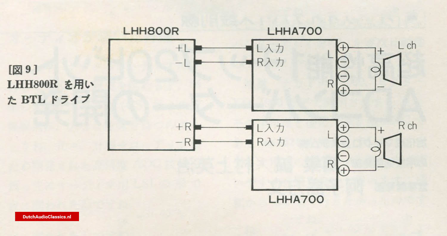
![Interview Tetsu Suzuki Philips LHH A700 Power Buffer Amplifier BTL drive configuration]() Philips LHH A700 Power Buffer Amplifier & LHH800r BTL drive configuration
Philips LHH A700 Power Buffer Amplifier & LHH800r BTL drive configuration
The block capacitors are arranged in four parallel units on each side.
Tetsu Suzuki:
Correct. By lowering the power supply impedance as much as possible, we improve current delivery. For that purpose, we use custom‑specified capacitors of 3,800 µF.
Enclosure structure and BTL drive configuration
The enclosure appears to be quite heavily constructed, with a considerable amount of metal used.
Tetsu Suzuki:
Yes. The enclosure uses thick aluminum panels, particularly on the top, where 30 mm thick extruded aluminum is used.
That must contribute significantly to rigidity.
Tetsu Suzuki:
It does. The rear panel, for example, uses 10 mm thick aluminum extrusion. Because of the relationship with the plated finish, we had to use thinner material in some areas, but rigidity was a major consideration throughout.
It does. The rear panel, for example, uses 10 mm thick aluminum extrusion. Because of the relationship with the plated finish, we had to use thinner material in some areas, but rigidity was a major consideration throughout.
Are the speaker terminals banana-plug compatible?
Tetsu Suzuki:
Yes. They are made by WBT in Germany, so they support banana plugs. The binding posts themselves are our own custom specification, with the material machined from brass and then gold-plated. The insulators are made from Teflon.
Earlier, we listened to the sound of BTL drive in combination with the Philips LHH800R. With BTL, the soundstage and resolution improved, and speaker control also became better. Even though the output impedance should theoretically double, the audible damping seemed improved.
Tetsu Suzuki:
Damping factor alone does not determine control. That is why our way of thinking had to change somewhat compared to conventional approaches.
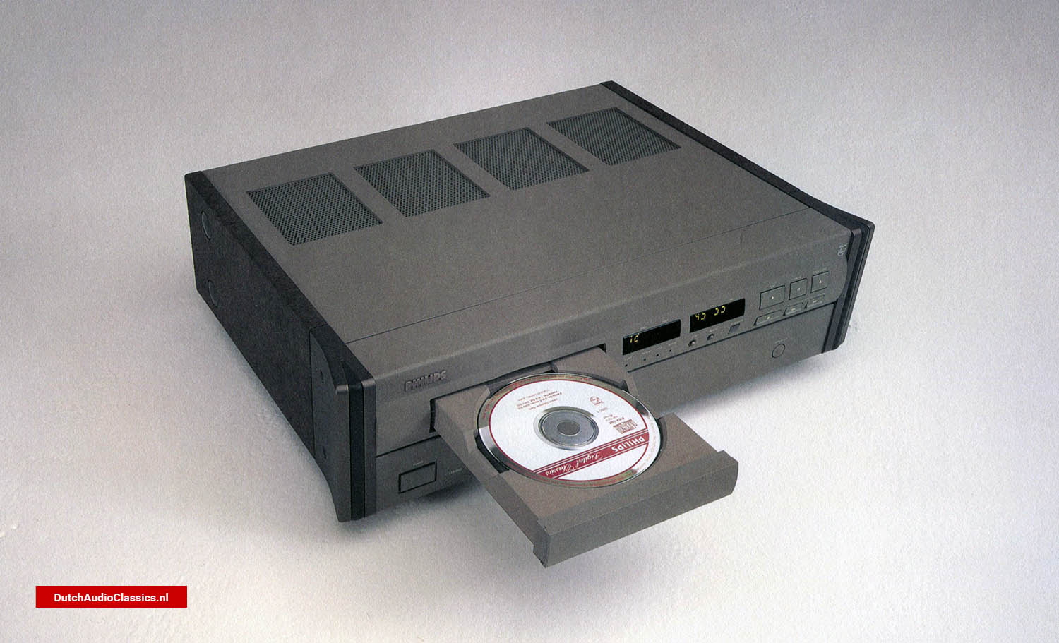
![Interview Tetsu Suzuki Philips LHH800r cdplayer]() Philips LHH800r cdplayer
Philips LHH800r cdplayer
The impression is that BTL drive gives the sound more substance and weight.
Tetsu Suzuki:
That is my impression as well. When considering digital devices such as CD players, the ground inevitably becomes somewhat contaminated. Driving speakers in a floating configuration brings significant benefits in that respect.
However, for BTL operation, the amplifier itself must have a well-defined ground. If that is not the case, it can instead introduce disadvantages.
With ordinary BTL configurations, an inverting amplifier is often added at the input.
Tetsu Suzuki:
In that case, one would not go so far with this design.
Does BTL operation improve low-frequency performance at the expense of high-frequency resolution?
Tetsu Suzuki:
Generally, BTL operation tends to increase distortion. That occurs because the phase response on the inverted side becomes a factor.
To gain the true advantages of BTL, the two halves must be identical except for phase inversion. Otherwise, only disadvantages appear. In some cases, there are systems where using the normal, non-BTL connection actually yields better results.
However, in the system we demonstrated today, two LHH A700 units were driven using the normal-phase and inverted-phase outputs of the LHH 800R, as shown in Figure 9. Because the timing of the normal and inverted signals is precisely aligned, the benefits of BTL are fully realized.
That makes clear the true significance of the LHH 800R having both normal and inverted outputs.
Tetsu Suzuki:
In the future, we are considering offering a separate BTL adapter that combines a preamplifier and BTL adapter as a standalone unit, so that higher-grade BTL systems can be built even with standard CD players.
That sounds promising. I look forward to it.
This page documents an interview with Tetsu Suzuki on the Philips LHH A700, covering its prototype origins and key design choices: feedback, bandwidth, stability, thermals, and BTL.
 Tetsu Suzuki
 Philips LHH A700 Power Buffer Amplifier
 Early prototype of the Philips LHH A700, used as the foundation for the amplifier’s final circuit and mechanical design.
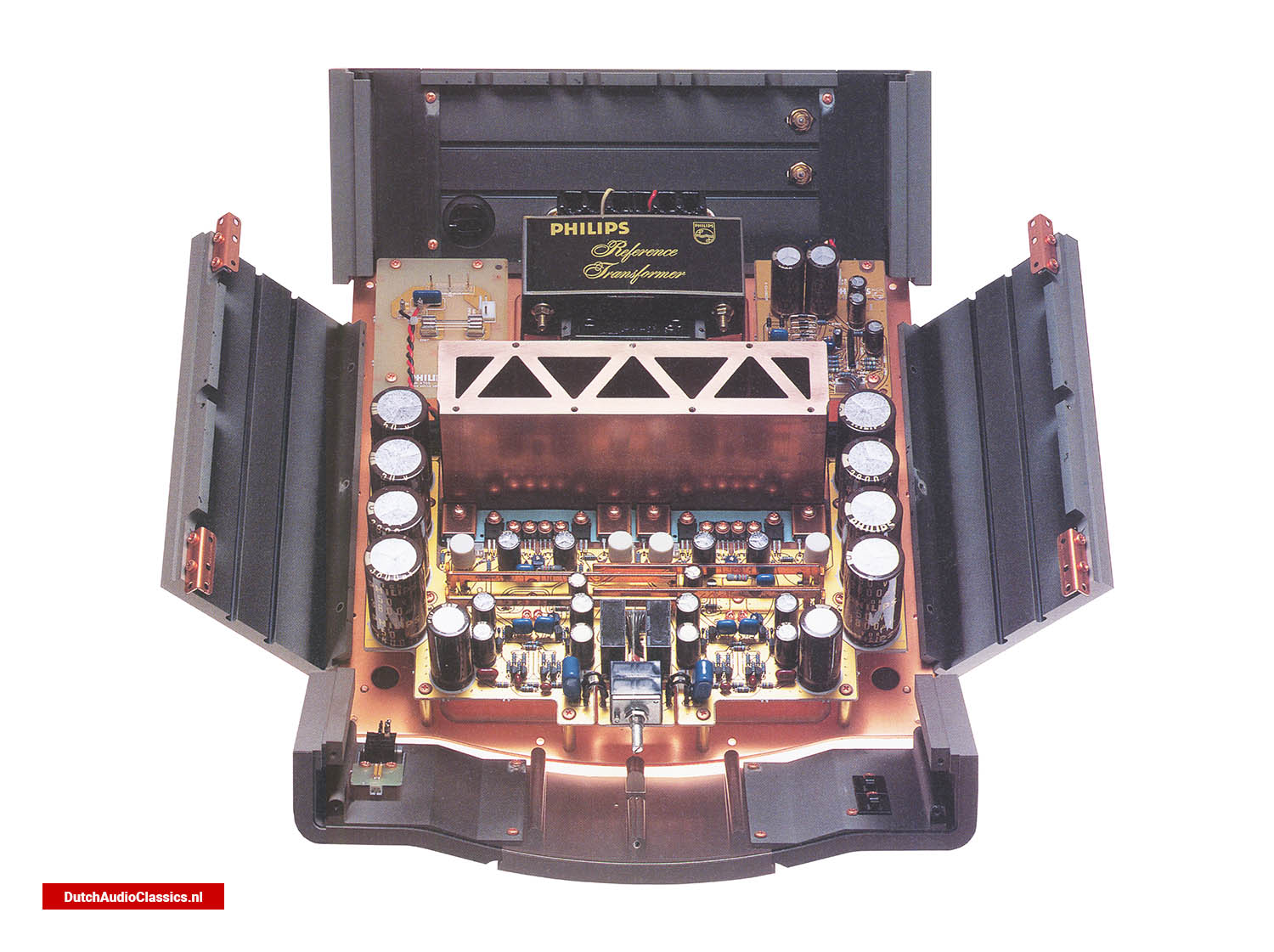
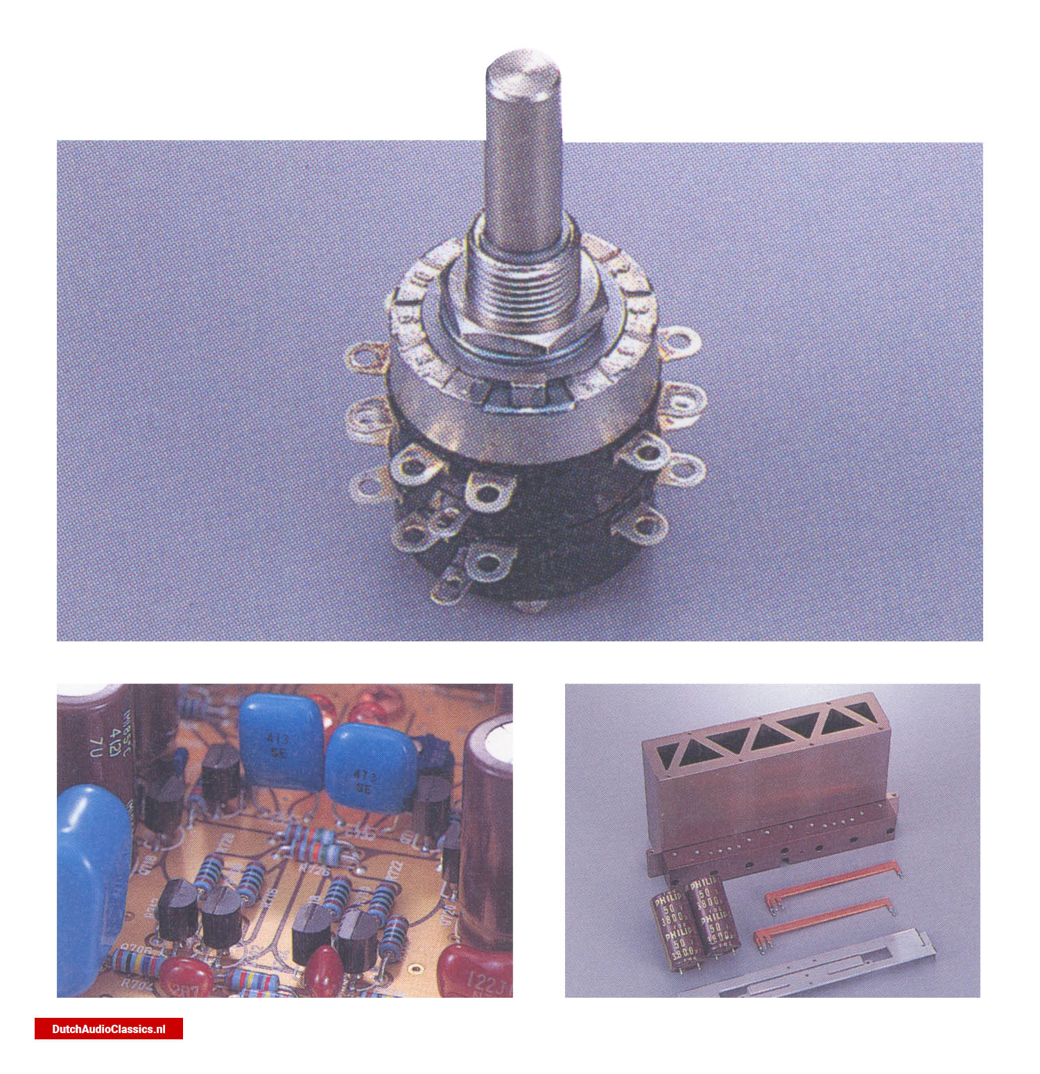
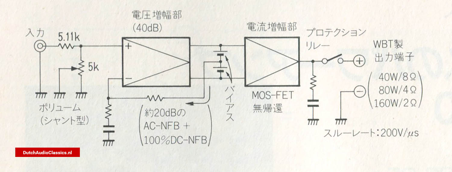 Figure 1 - Philips LHH A700 signal path
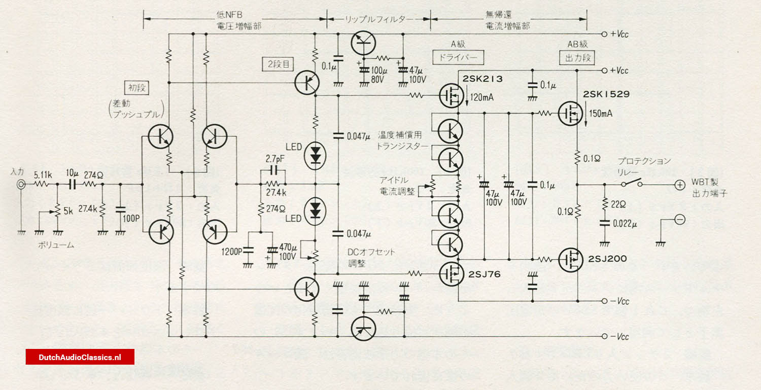 Figure 2 - Philips LHH A700 circuit configuration of the voltage amplification stage
 Figures 4 t/m 9
 Philips LHH A700 Power Buffer Amplifier & LHH800r BTL drive configuration
 Philips LHH800r cdplayer