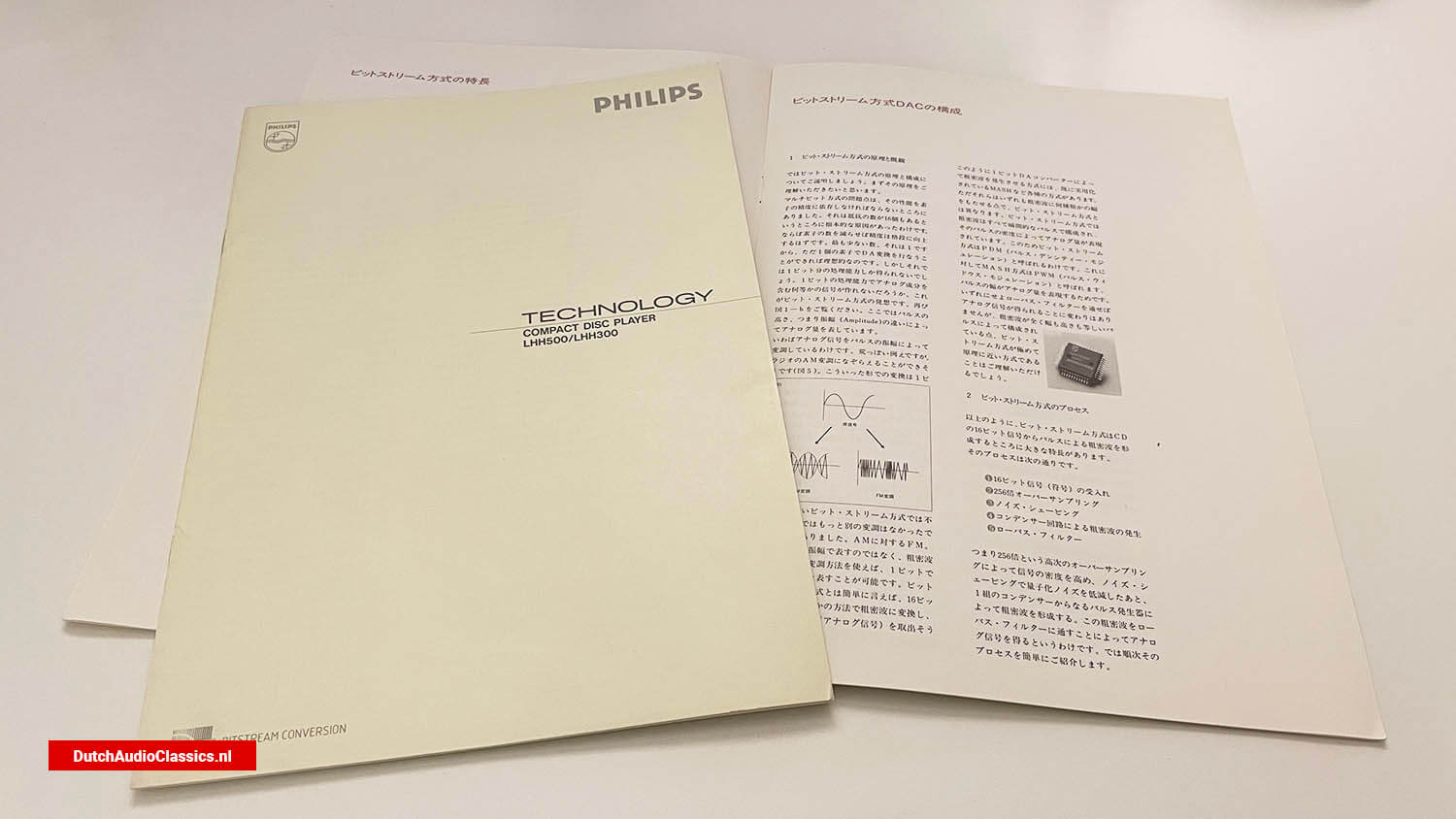
Digital recording is a way of expressing sound in coordinates. For example, suppose you have a curve like that shown in Fig. 1-a. You could transcribe it, or trace it on a thin sheet of paper. However, this would always lead to errors after several repetitions. However, if you set the vertical and horizontal axes and record the coordinates of the required points, you can always recover them accurately. This is exactly how digital recording works. In contrast, tracing on a piece of paper is an analogue method.
The Philips Bitstream method An introduction
Digital recording and conventional DA converters
1. Concept of digital recording
So what should you set as the coordinates? One is time. Another is the level, i.e. the loudness of the sound. In other words, the sound is represented by coordinates with time on the horizontal axis and sound level on the vertical axis.
The basic idea behind digital recording is to represent sound on a coordinate scale, with time on the horizontal axis and the loudness of the sound on the vertical axis. On a CD, the horizontal axis (time) is divided into 1/44,100 seconds. This means that a voltage is recorded every 1/44,100 of a second. How should the voltage itself be delimited? Ideally, it would be infinitely fine, but this is not possible. In CDs, this is done by dividing the voltage into 65,536 steps, i.e. 16th power of 2. In other words, what is recorded in a digital recording is the position of the sound volume in 1/44,100th of a second in the 65,536 steps.
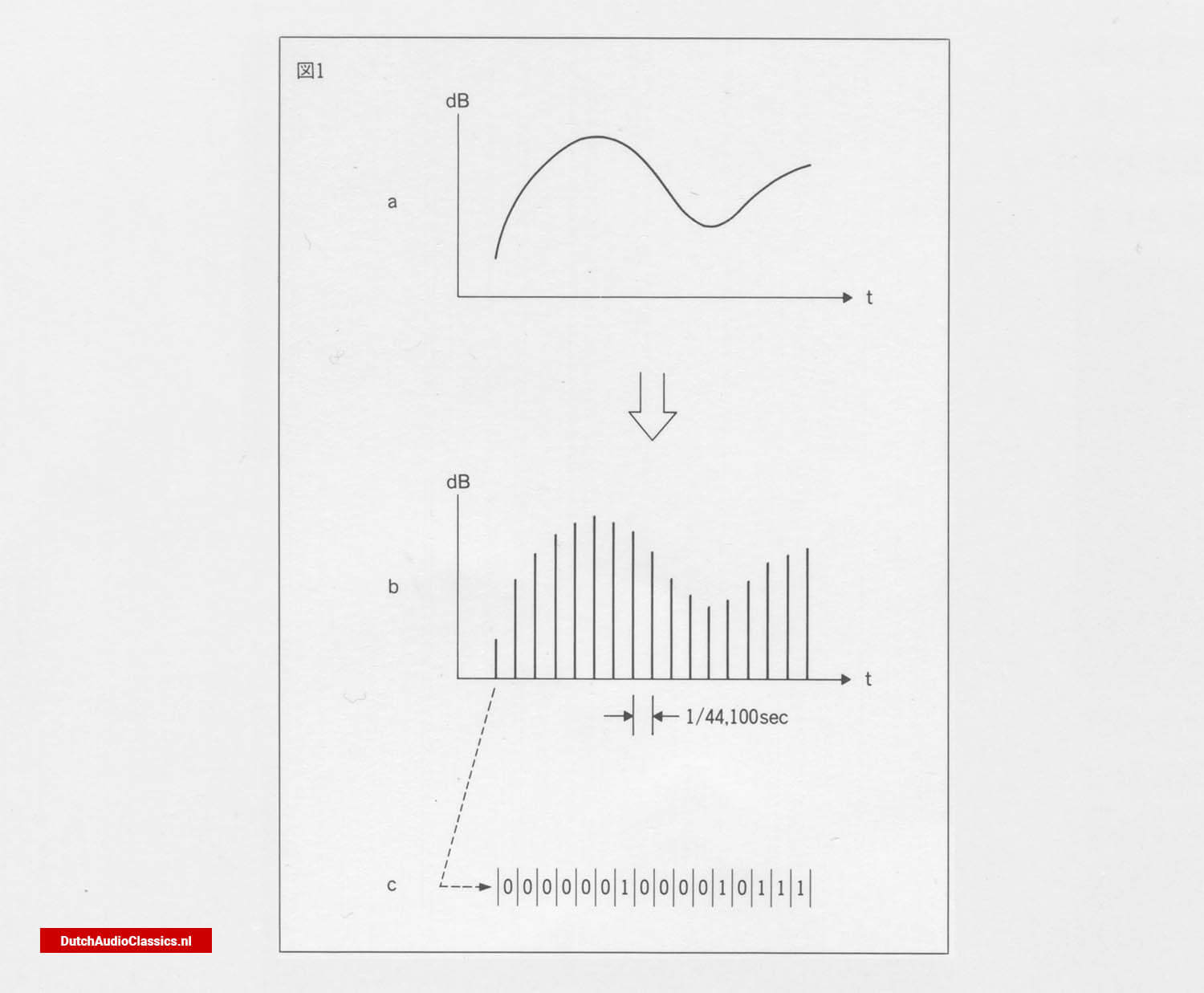 Fig. 1 - This relationship is illustrated in Fig. 1, day 1. It is clear that the loudness of the sound in each celestial interval corresponds to the original curve. The CD does not directly record this as the loudness of the sound. The method used is to put a sign on the loudness of the sound, or actually the voltage, and record the sign. This code uses a 16-digit binary number, i.e. a number consisting of only 0s and 1s (Fig. 1-c).
CD playback is nothing more than the reverse of this process, reading the 0s and 1s from the presence or absence of pits (Fig. 1-¢), converting the waiting signal into a moment-by-moment voltage magnitude (Fig. 1-b) and finally restoring the analogue signal.
2. Conventional DA conversion methods
Aside from reading the code, how do you convert a signal made up of 0s and 1s into a voltage quantity? A circuit called a DA (digital-to-analogue) converter does this.
Conventional DA converters (called multi-bit systems) operate in the following way. Simply put, it is a parallel circuit with 16 resistors, each with its own switch. The resistors have a resistance value of 1/2 in that order. Since there are 16 of them, there is a difference between the smallest and the largest by a factor of 2 to the 15th power = 32,768. The current values flowing through them are the opposite, so they are halved in that order. And each of these 16 corresponds to 16 digits of the sign (Fig. 2).
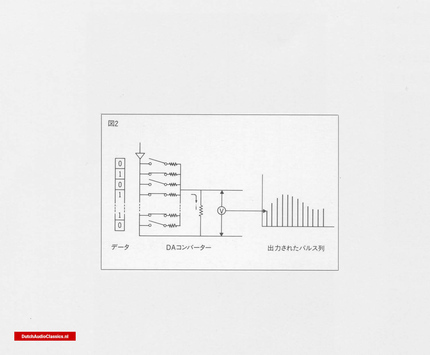 Fig. 2
For example, if the first digit of the line number is 0, the switch remains open and no current flows. If it is 1 again, the switch closes and current flows. This operation is carried out simultaneously for 16 digits.
What happens then? The current flowing through each resistor is doubled. And depending on their combination, they can represent all numbers from 0 to 65,635.
This is the same as, for example, a combination of 1 yen, 2 yen, 4 yen and 8 yen stamps, which can represent all amounts from 0 yen to 15 yen. In other words, a multi-bit DA converter is a mechanism that uses a combination of 16 resistors to generate any current from 0 to 65,535 steps.
The current thus obtained is converted into a voltage, as shown in Fig. 116. As this signal is an intermittent pulse, it is not a sound. However, as can be seen at a glance, this waveform can be regarded as a synthesis of a low-frequency audio signal and a high-frequency pulse signal (Fig. 3). By removing the high-frequency components, only the low-frequency components can be extracted from such a signal. This is done by a low-pass filter, and the signal of Fig. 11a is restored to its original waveform of Fig. 11a by passing through a low-pass filter that cuts off 20 kz or more.
 Fig. 3
3. Accuracy of multi-bit systems
As described above, the multi-bit method is a very reasonable and stable DA conversion method, but there is one problem. The accuracy of the DA converter itself is highly dependent on the accuracy of the circuit elements. In other words, there is a gap of 35,768 times between the smallest and the largest resistor. This accuracy must therefore be maintained for accurate DA conversion. Of course, extremely high accuracy can be achieved using a high-quality DA converter such as the Philips TDA1541A-S1. (used in Philips LHH1000, Marantz CD-95, etc.), but it is, after all, costly, and no matter how high the accuracy is, it will not result in an ideal straight line.
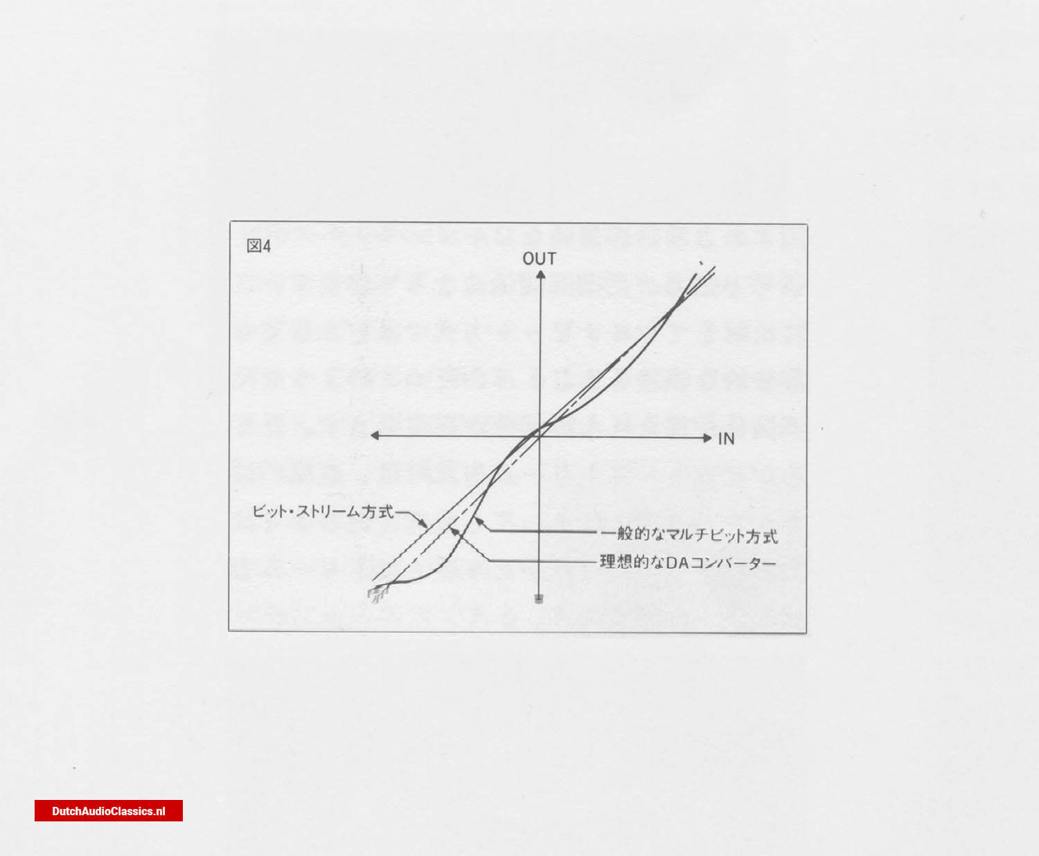 Fig. 4 - This means that there is inevitably a certain amount of error. The trouble is that this error is particularly noticeable on the micro level, i.e. in the smallest parts of the sound. Is there a way to avoid such errors in principle? That is the bit stream method.
Features of the bit stream method
1. Excellent linearity
The voltage that comes out corresponding to the code read from the CD does not exactly correspond to that code. This condition is called 'poor linearity'. And the distortion caused by such a phenomenon is called 'non-linearity distortion'. Is there any DA converter that, in principle, does not produce non-linearity distortion? The bit stream method was developed with this in mind. As a conclusion, the bit stream method does not cause non-linearity, even though the level may rise or fall.
As shown in Fig. 4, in an ideal DA converter, the signal and output are directly proportional. In contrast, in a multi-bit system, partial errors inevitably occur and, therefore, parts of the system where such a proportional relationship is not maintained. In the bit stream method, however, the slope of the line may change, but it does not lose its linearity. This is the greatest feature of the bit stream method.
2. Less distortion at the micro level
The good linearity of the sound means that distortion at the micro level, which is so often heard in the past, is noticeably reduced. This means that even in pianissimo passages, individual instruments can be clearly distinguished, and the extra amount of sound and subtle nuances can be heard even more clearly. The clarity and atmospheric sound of the bit-stream method is a characteristic of its sound quality.
3. Smooth, connected sound
Another feature of the sound quality is the smooth, well-connected sound. This is due to the fact that, in principle, non-linear distortion and zero-cross distortion do not occur. This means that the subtle components in each sound, such as overtones, can be reproduced without any muddiness, resulting in the reproduction of a smooth, well-connected sound.
4. Resistant to temperature change and secular change
Temperature change is a major enemy of semiconductor devices. This is because the operating characteristics change slightly depending on the temperature. Temperature changes are constantly occurring inside audio equipment due to the flow of electric current. Changes in the characteristics of the device over time cannot be overlooked either. The bit stream method uses fewer elements and has a simpler structure, so it is extremely resistant to temperature changes and changes over time. This means that there are no fluctuations in operating characteristics due to changes in flow, which is a factor supporting the high linearity of the system. The low variation over time also guarantees long-term durability.
Musical and delicate sound quality
The sound quality of the Philips cdplayers with Bitstream conversion can be described in one word: highly musical sound supported by rich nuances. This is the result of the low distortion and high linearity characteristic of bit stream systems, combined with the unique expressiveness of the music itself.
Configuration of a bit-stream DAC
1. Principle and overview of bit-stream systems
Let us now explain the principle and configuration of the bit-stream method. First of all, we would like you to understand the principle.
The problem with multi-bit systems was that their performance had to depend on the precision of the elements. The fundamental cause of this was the fact that there are 16 resistors. Then, if the number of elements is reduced, the accuracy should improve dramatically. The lowest number is 1.
Therefore, it would be ideal if DA conversion could be carried out with just one element. However, this would only give a processing capacity of 1 bit.
Couldn't we create some kind of signal with an analogue component with the processing power of one bit? This is the idea behind the bit stream method. Again, look at Fig. 1-b.
Here, the analogue quantity is represented by the difference in pulse height, or amplitude (Amplitude). In other words, the analogue signal is modulated by the amplitude of the pulses. This is a rough analogy, but it can be likened to AM modulation on a radio (Fig. 5). This form of conversion is not possible with bit stream systems, which have only one bit. So was there not a more alternative modulation? There was: FM as opposed to AM.
Using a modulation method in which the analogue quantity is not expressed in amplitude but in coarse and dense waves, it is possible to express analogue quantities even with one bit. Simply put, the bit stream method converts a 16-bit code into coarse and dense waves in some way, from which the original signal (analogue signal) can be extracted.
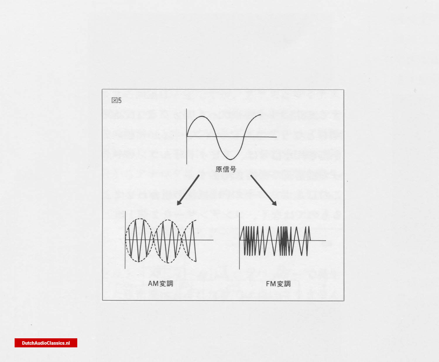 Fig. 5
There are various methods for generating coarse and dense waves with a 1-bit DA converter, such as MASH, which is already in practical use. However, they differ from the bit stream method in that they all generate a range of coarse and dense waves. In the bit stream method, the coarse and dense waves are all composed of instantaneous pulses, and the analogue quantity is expressed by the density of these pulses. For this reason, the bit stream method is called PDM (pulse density modulation). In contrast, the MASH method is called PWM (pulse widow modulation). This is because the width of the pulse expresses an analogue quantity. In any case, the fact remains that an analogue signal can be obtained by passing a low-pass filter.
However, you can see that the bit stream method is very close to the principle in that the coarse and dense waves are made up of pulses of exactly the same width and height.
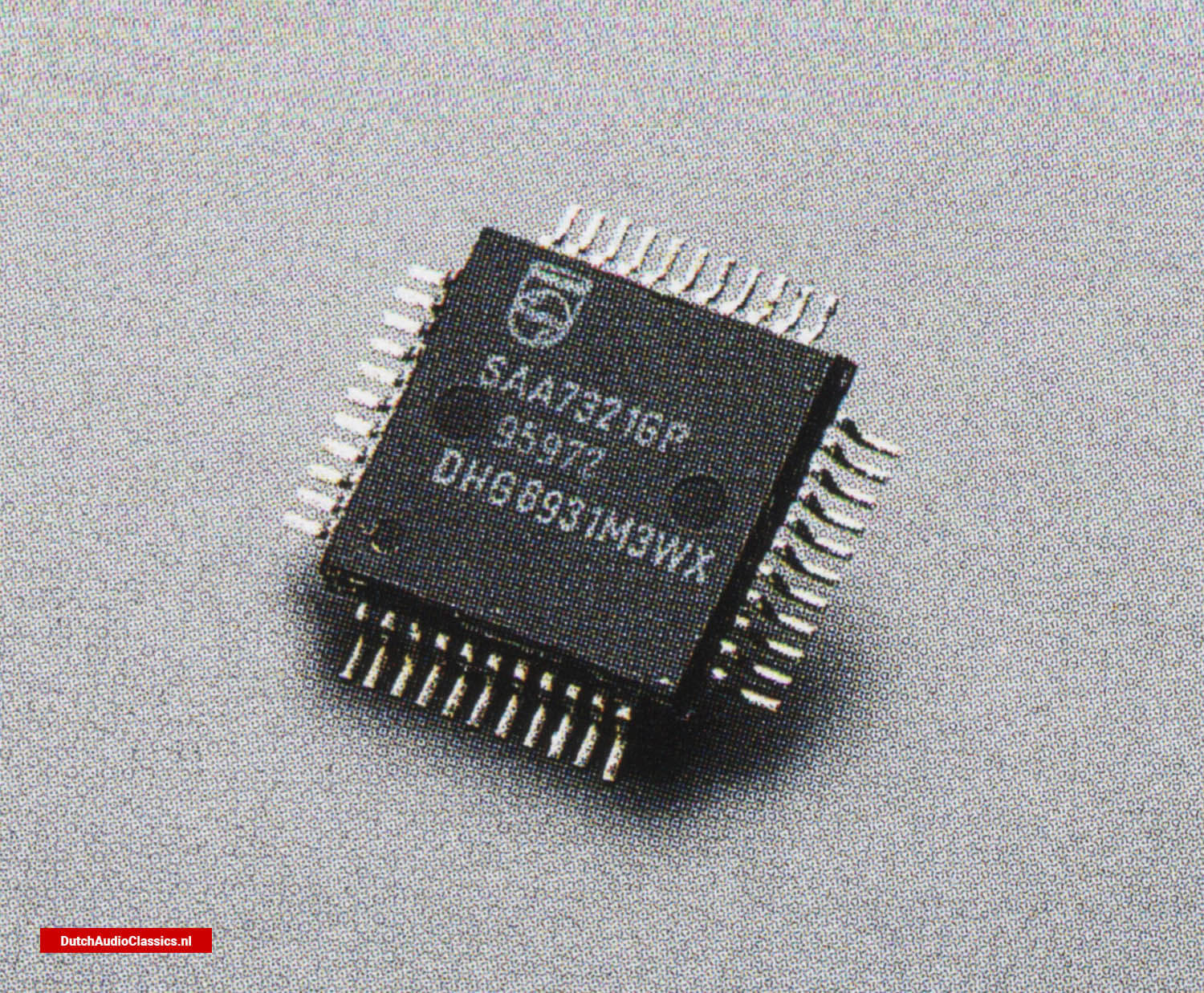 Philips SAA7321GP Bitstream DAC
2. Process of the bit stream method
As described above, the bit-stream method is a process that is based on the 16-bit wacceform of a CD
The process is as follows.:
1) Acceptance of 16-bit signal (code)
2) 256-fold oversampling
3) Noise shaping
4) Generation of coarse and dense waves by a capacitor circuit
5) Low-pass filter
In other words, after increasing the density of the signal by high-order oversampling (256 times) and reducing quantisation noise by noise shaping, a low-pass filter is used.
A pulse generator consisting of a pair of capacitors is used to form a coarse-dense wave. This coarse-dense wave is then passed through a low-pass filter to obtain an analogue signal. The process is briefly explained in turn below.
3. 256-fold oversampling
Oversampling itself is not particularly uncommon. Oversampling by a factor of 4 or 8 is already common practice. However, whereas oversampling in multi-bit systems is used to soften the cut-off characteristics of the final low-pass filter, in bit-stream systems it has the effect of increasing the density of the coarse and dense waves. This is why extremely high-order oversampling of 256 times is used.
In practice, a 16-bit signal is stored in memory and aligned to 16 digits. The data is then compared with the next data to fill in the gaps (Fig. 6). So it is not simply a case of repeating the same signal 256 times. This operation results in an apparent sampling frequency of 11.2896 MHz. seconds, which means that 11,289,600 pulse signals are lined up per second.
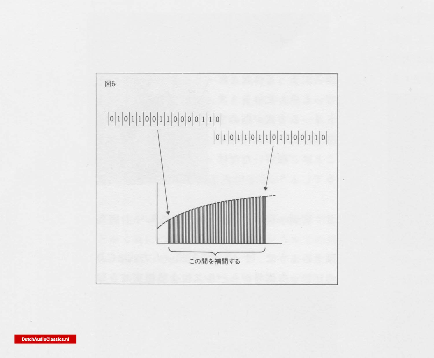 Fig. 6
4. Noise shaping
Noise shaping can be thought of as a kind of digital feedback. The reason why this is necessary is that the sign is actually truncated as it enters the DA converter.
During oversampling, the 16-bit signal is transformed into a 32-bit signal when it passes through the digital filter. So the signal actually entering the DA converter is 32 bits. Only the upper 16 bits of that are used and the remaining 16 bits are discarded. This is the same in the case of 16-bit, and also in the case of 18-bit and 20-bit high-bit systems.
The truncation is the amount of error. The noise shaping method is to carry over the truncated bits to the next data one after the other, in order to make the data as level as possible. It is similar to negative feedback in amplifiers.
With noise shaping, quantisation noise (error distortion), which used to be uniformly distributed over the entire bandwidth, is now heavily biased towards the high frequencies, and quantisation noise is drastically reduced in the bandwidth up to 20 kHz (Fig. 7).
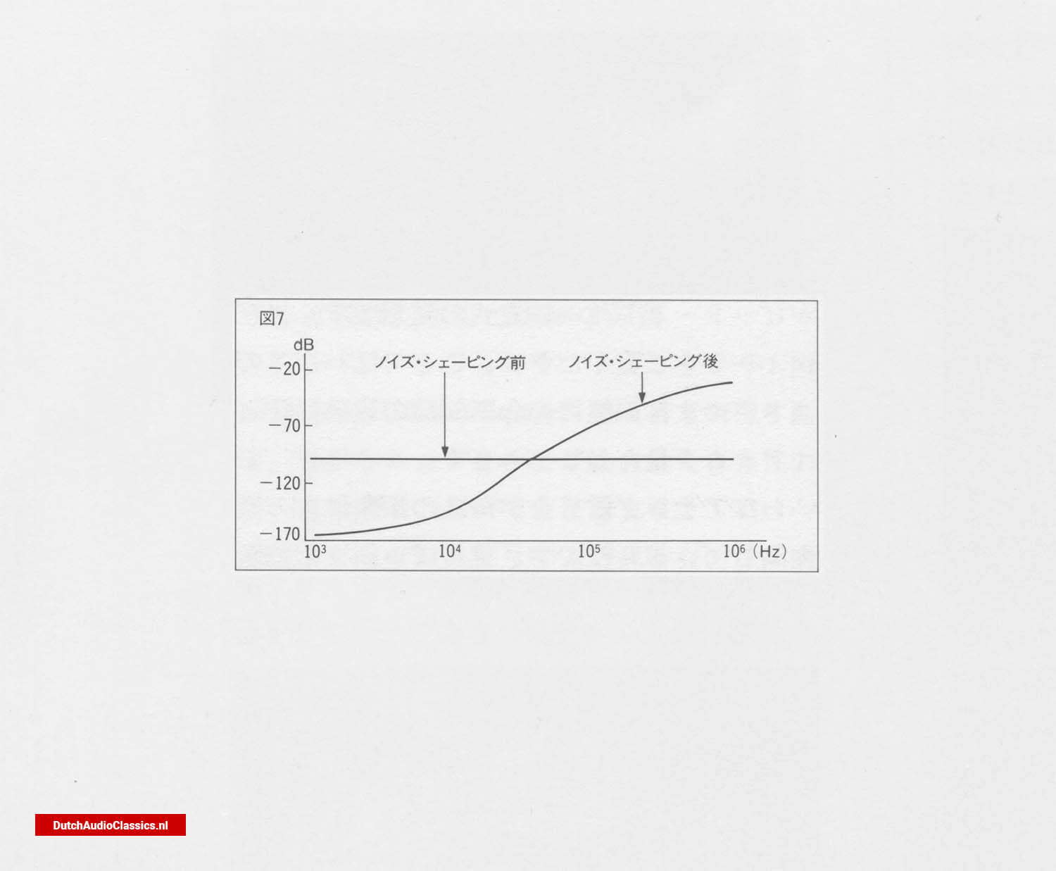 Fig. 7
5. Generation of coarse and dense waves by a capacitor circuit
Now, with 256-fold oversampling at 11.2896MHz and further noise shaping is applied to the signal, which is converted into a coarse and dense waveform by a 1-bit DA converter.
The signal is converted into coarse and dense waves in a 1-bit DA converter. This DA converter is not a combination of resistors, but a simple circuit using two pairs of capacitors. The two capacitors are repeatedly charged and discharged according to the clock, generating pulses (Fig. 8).
By the way, as audio signals are alternating current, these pulse coarse and dense waves must also have a positive and a negative value. How are they differentiated? There are 256 pulses corresponding to a single piece of data, so it is not possible to determine which of them should be positive and which negative. In fact, the pulse signal generated here is a 16-bit signal.
Please note that the pulse signal generated here is not 256 times the 16-bit pulse signal. The data for pulse generation is read from ROM.
The ROM has a memory of pulse generation patterns corresponding to various signals (CD's contributions). In other words, this pattern is always fixed when a signal of this shape is received. Based on this pattern, the DA converter generates pulses. This naturally includes the positive/negative distinction. Unlike FM, the pulses generated in this way have a constant pulse interval, but the positive and negative pulses are altered, resulting in coarseness and density.
Fig. 8
This coarseness and density corresponds to the original analogue signal. Thus, the original aim of generating some kind of signal containing an analogue quantity from a 16-digit code was achieved.
6. Low-pass filter
The dense wave generated by the bit stream DA converter is not a sound by itself. This is because they are modulated by a high-frequency component called a pulse. If this extra high-frequency component is removed, a smooth analogue signal should be obtained.
The multi-bit field also passed through a low-pass filter at the end, but here, too, it is possible to remove the high-frequency component by passing it through a low-pass filter. In the bit stream method, the analogue signal is obtained by passing it through a relatively simple third-order low-pass filter and cutting off unwanted high-frequency components. The original audio signal is thus restored (Fig. 9).
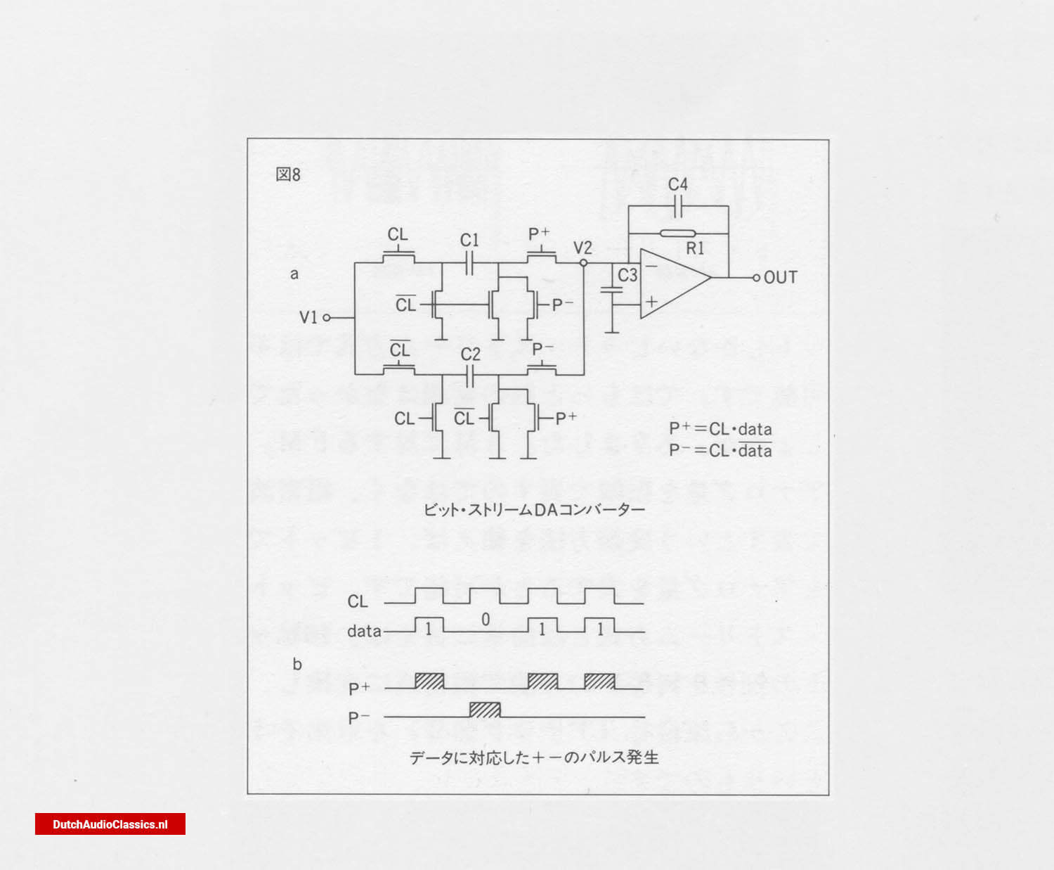 Fig. 9
Both the Philips LHH500 and Philips LHH300 are both CD players equipped with bit stream DA converters, but they do not simply employ a new DAC system. Two of these are used.
1. Features of differential mode
Differential mode is already familiar in amplifiers. The differential mode amplifies only the difference between the human forces applied to a pair of amplifying elements. It is extremely stable against humidity changes and noise and is therefore widely used today.
The differential mode handles the difference between the inputs to the two amplifying elements, so any in-phase components between them will be cancelled out. This is the case, for example, with noise. Noise that is discarded while passing through the circuit is input to both elements as a component of the same phase, so it is eliminated by subtraction, so to speak. Also, semiconductor elements change their characteristics depending on the temperature at which they are operating, but the temperature change is also the same for the two elements. Therefore, even if there is a change in the characteristics, it is cancelled out, so the device has excellent stability against this type of characteristic change. This differential mode is used in the Philips LHH500.
2. Differential mode DA converter
A differential mode DA converter is one in which the signal from one channel is fed into the converter in the reverse phase and the difference between the signal in the positive phase is taken as the output.
The bit stream DAC chip used in the Philips LHH500 and Philips LHH300 is considerably smaller than its predecessors. Therefore, coexistence of L/R channels in one chip may increase separation and mutual interference distortion. The differential mode cleverly avoids this by feeding the L/R channels into completely separate chips. One chip is then fed with the positive and reverse phase components of one channel, and the difference is taken as the output.
Clearly, this configuration is far superior when considering distortion and noise, as well as separation and interference between channels.
3. Differential mode DAC configuration
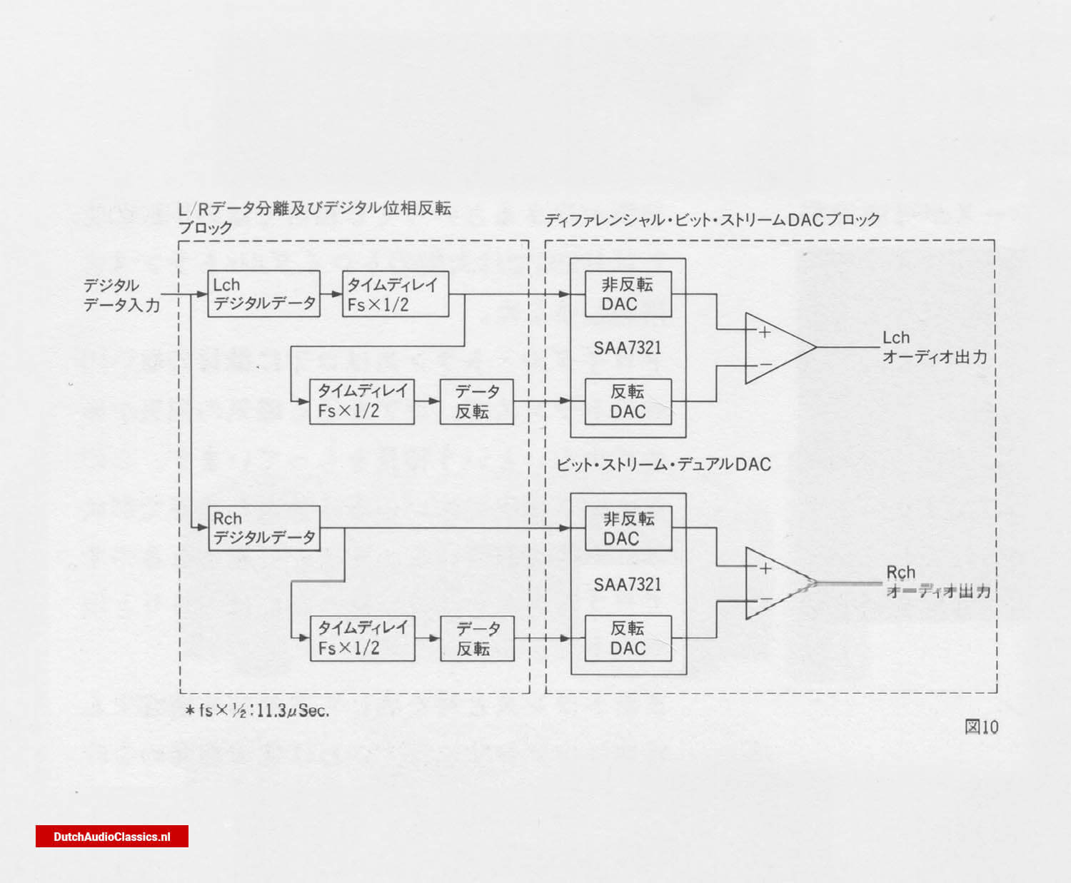 Fig. 10
The signal read out from the CD is processed by the DA converter through the following process.
1) L/R data select.
A CD contains alternating L/R channel signals. Therefore, these two must first be separated. This is the data select. In the case of Philips, the L channel comes first, so in order to align the two channels, the L channel must be set to fs x 1/2 time, i.e. half of 1/44,100 s. Only the L channel has one time delay. This is why only the L channel has one extra time delay.
2) Formation of inverted and non-inverted data
As a result of delaying only the L channel, the timings of both channels are now aligned, so two types of data can now be created. One is the non-inverted data, which is the data as it is. On the other hand, inverted data is created. This is inverted data delayed by a further time delay of fs x 1/2, which forms the inverted data.
3) DA conversion and output synthesis.
The inverted/non-inverted data of the L channel and the inverted/non-inverted data of the R channel are input to the DA converters separately. In other words, there are four DA converters. The inverted/non-inverted output of each channel is then combined with the inverted/non-inverted output converted to analogue.
The signal output in this way is the difference between the inverted and non-inverted outputs, so any identical components between them, e.g. noise such as hum or even harmonics, are cancelled out, resulting in a signal of extremely high purity.